

I’ve seen many capable operators ruin perfectly good sheet metal. They position a fresh blank against the backgauge, press the pedal, and complete the first bend perfectly. They flip it, press the pedal again, and complete the second. Two clean 90-degree flanges. They glance at the print, feeling confident.
Then they attempt to bring up that third flange.
Suddenly, the metal they already formed starts wrapping around the punch like a steel cage. The ram blocks the movement. The part becomes trapped. And they realize they haven’t been building a box—they’ve been creating a trap for their own hands.
Here is the blunt reality: most operators approach box bending as a simple forward sequence, but that flat-world reasoning will inevitably cause a crash. To avoid the unavoidable collision—when the part reaches about 45 degrees and the previously formed flanges swing directly into the upper tooling—you must stop bending in order. Forming a box successfully requires reverse-engineering the process from the fourth bend backward. If you don’t plan your final clearance first, you are simply producing expensive scrap.
Related: Smooth Press Brake Bending
Related: Press Brake Basics
The “First Two Bends” Trap: Why Box Bending Feels Misleadingly Simple
Why “just following the print” works for flat brackets but fails with boxes
Look at a typical Z-bracket on a blueprint. You read it from left to right. You bend flange A, flip the part, and bend flange B. The flat-world logic works because the unbent portion of the blank remains flat and parallel to the floor. The machine’s open height is rarely a concern. The ram clears everything. You can follow the print step by step all day without striking solid steel.
But a box print misleads you.
It displays four sides unfolded like a cross. If you follow that cross clockwise, or apply the same approach you use for a flat bracket, you are relying on a 2D assumption in a 3D situation. The first two bends let you think it works. You bend the left side up. You bend the right side up. Now you have a clean U-shape. The trap is already in place.
The geometric shift: What actually changes once the part leaves the flat plane
Take a rigid piece of cardboard, fold two opposite ends upward, and pinch the flat bottom. Now try to fold a third side up without letting those first two walls strike your wrist.
That wrist represents your punch. With a flat bracket, the metal swings upward into open space. With a box, the moment you begin that third bend, the two flanges already formed start sweeping inward toward the tooling. The blank is no longer simply a flat sheet resting on the V-die. It now has vertical walls. And those walls are in motion.
You are no longer only changing the bend angle of the metal. You are using up the open space surrounding your tooling.
Recognizing the Precise Moment Your Workpiece Shifts from Flat Sheet to Collision Risk
That shift does not occur when you press the pedal for the third bend. It occurs the moment you commit to your die selection for the first bend.
If you are forming a box with short flanges—under four times the material thickness, for example—those flanges may drop slightly into the V-die during the first bend. Or your blank may have a slight bow, misleading the backgauge center stops while the ends lift away. With a flat bracket, you can force a bowed blank through or later correct an overbent angle by flipping and unbending it on the same brake.
In a box, however, a bowed blank or a short flange dropping on the first bend means the resulting U-shape is already out of square.
By the time you rotate the part 90 degrees to begin the third bend, those out-of-square walls are no longer merely a tolerance concern. They are directed straight at your ram. The collision risk does not originate when the metal finally scrapes the steel. It originates the moment you close the first two sides without providing a defined escape path for your tooling.
The 45-Degree Collision Problem: What Your Box Is Attempting to Strike
Picture a U-shaped part positioned on your V-die. The side walls are six inches tall. You press the pedal to start the third bend. The punch makes contact with the flat bottom and drives it into the die. As the metal yields, the entire U-shape rotates. At the midpoint of that stroke, those six-inch walls are no longer vertical, nor are they flat. They are angled inward at 45 degrees, closing like a large steel claw around your upper tooling.
The collision almost never occurs at the bottom of the stroke. It occurs precisely halfway through.
Modern press brakes are extremely precise, capable of repeating ram positions within 0.0005 inches under heavy tonnage. That level of precision is impressive, but it will not prevent this issue. Machine accuracy does not alter physics. You may have the most finely tuned crowning system available, but if you handle a box as though it were a flat bracket, a crash will occur. The problem is not a failure in the machine’s execution. It is the operator’s failure to account for the geometry of the swing.
Given that ADH Machine Tool’s product portfolio is 100% CNC-based and covers high-end scenarios in laser cutting, bending, grooving, shearing, for teams evaluating practical options here, CNC Press Brake is a relevant next step.
But what is the mathematical explanation behind that closing claw?
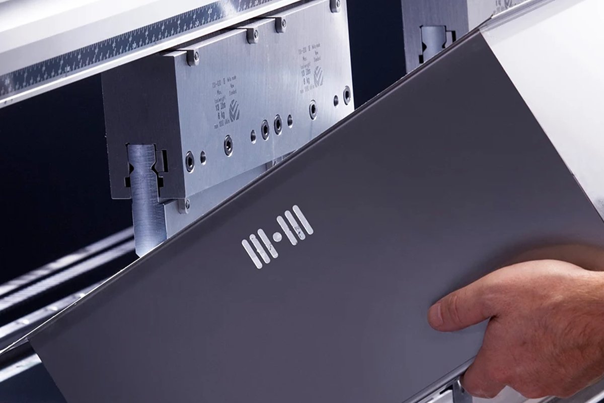
The mid-stroke swing: Why the return flange abruptly targets the upper ram on the third bend
Let’s examine the geometry of that third bend. When you form the third side of a box, the first two sides—the return flanges—rotate upward. At the beginning of the bend, they are parallel to the floor. When the bend reaches 90 degrees, they are parallel to the punch. At 45 degrees, however, they extend inward to their maximum reach toward the ram’s centerline.
Picture it as a right triangle. If you are bending a box with six-inch-deep sides, at 45 degrees the top edge of the return flange swings inward by about 4.2 inches.
If your upper ram or punch body occupies that 4.2 inches of space, the metal has nowhere to move. The flange collides with the tooling mid-stroke. The machine continues to apply force, the tonnage rises sharply, and the ram stalls. You end up with more than a scratched part. You have a ruined blank, a distorted bend angle, and a piece of steel wedged so tightly against the upper beam that you often must unbolt the punch just to release the jam you created.
How can you determine whether your machine has enough physical space to accommodate that inward sweep?

Open height vs. box depth: Calculating your actual clearance limits before the die closes
You check your press brake specifications and see an “open height” of 18 inches. It appears to provide ample room for a six-inch box.
Open height can be misleading if misunderstood. It does not represent empty working space. It is simply the maximum distance from the bed to the ram without tooling installed. After installing a standard four-inch V-die, a six-inch punch, and the clamping system that secures them, your 18 inches of daylight may be reduced to roughly five inches of usable clearance.
When the third bend swings upward, the total depth of your box must be less than the height of your punch plus whatever daylight remains beneath the clamps. If your box is six inches deep and your punch is only six inches tall, the calculation is already at its limit. As soon as the die closes, the top edges of the box will rub against the underside of the ram clamps. You are not only controlling the metal; you are also controlling the negative space surrounding it.
For readers who want exact machine dimensions, open heights, punch clearances, and configuration options to validate these calculations against real equipment, ADH Machine Tool provides detailed technical documentation for its CNC press brake and sheet metal solutions. You can review specifications, tooling compatibility, and capacity data in the official downloadable brochures here: Download the technical brochures.
And when that negative space is exhausted, the metal will strike the thickest steel in its path.
Why standard straight punches and typical clamping heights inevitably fail with box geometry
Walk through the tooling rack of an average fabrication shop and you will see rows of standard straight punches. They are thick, rigid, and well suited for applying heavy tonnage to flat brackets.
However, a straight punch has a wedge-like form. It becomes wider as it rises toward the tang. When applied to a box, this expanding shape functions like a wedge forced into a funnel. The 4.2-inch mid-stroke swing we calculated carries the return flanges directly into the thickest section of the punch body. In that moment, the punch itself turns into the obstruction.
This is precisely the reason gooseneck punches were developed. A gooseneck includes a recessed neck—an actual cutout in the steel profile—designed to allow a formed wall to swing past the ram’s centerline without making contact. It provides the clearance that a straight punch effectively removes. Yet even with a gooseneck, standard clamping heights can undermine the operation. If the punch is not tall enough to keep the clamps outside the collision zone, the recess offers no benefit. The box may clear the punch, only to collide with the clamp instead.
Standard tooling is based on the assumption that the metal will always move away from the machine. Box geometry requires the metal to wrap around it instead. When your tooling is certain to be enclosed by the very material it is shaping, you cannot simply hope the flanges will clear that 45-degree swing on the final stroke. The only way to avoid that unavoidable collision—without crushing a flange or permanently trapping your punch inside the finished part—is to stop reading the print as a left-to-right set of steps. You must anticipate the trap you are about to create, move directly to the final bend in your thinking, and reverse-engineer the entire sequence from that point.
Stop Bending in Order: Reverse-Engineering from the Fourth Bend
Picture a standard 4x4x4-inch electrical junction box made from 16-gauge carbon steel. You lift the flat, cross-shaped blank and bend the North side, then the South, then the East. Everything appears fine until you press the pedal for the West side.
The ram descends, the final flanges swing upward, and the metal closes neatly around your upper punch. You have just constructed a steel enclosure with your machine’s tooling trapped inside.
To remove the part, you must reach for a wrench, unbolt the punch, and slide it out from the side. You did form a box, but you did not succeed as a fabricator. A box cannot be bent in alphabetical sequence. You have to begin with the end in mind.
If the final bend is the most restrictive, why not base the entire sequence on it?
The fourth bend is the only stage in the process where the tooling is enclosed by metal on all four sides. If your sequence is not built around surviving that specific stroke, the rest is irrelevant.
Examine the physics of springback in a ductile material such as A36 carbon steel. To achieve a true 90-degree corner, you must overbend slightly. You drive the punch until the metal reaches 88 degrees, allowing it to relax back to 90 degrees when the ram retracts.
Here is the complication: when you overbend that final side, the two neighboring walls do not remain perfectly vertical. They lean inward toward the punch body.
The Takeaway: If you have not provided sufficient clearance for that 2-degree inward lean, the box will physically resist. It will bind against the tooling before the bend is fully completed.
Some CNC shops attempt to bypass this geometry by using “N-folding.” They intentionally under-bend the first three sides to around 93 degrees. This keeps the box slightly flared open, providing the punch with enough clearance on the final hit. After that, they return to square everything up.
It is a clever method of building in forward allowances to accommodate collision geometry, but it carries a cost. Re-striking bends consumes time and creates significant tolerance stacking errors.
Given that ADH Machine Tool’s product portfolio is 100% CNC-based and covers high-end scenarios in laser cutting, bending, grooving, shearing, for additional context, see Smooth Press Brake Bending.
A true craftsman does not depend on imprecise initial angles to preserve the final hit. You control the clearance window by deliberately selecting which flanges to fold first.
Short sides first or long sides first: How flange length determines your clearance window
Take a print for an 8-inch by 4-inch rectangular chassis. It has two long sides and two short sides.
If you bend the 8-inch sides first, you form a long, narrow channel. When you then bend the 4-inch sides, the punch must fit completely inside that narrow channel. If your tooling is even slightly too wide, it will rub against the inside of the already formed long flanges.
Example: This is precisely why wiping bends—where the die block pushes the metal upward instead of air-bending it into a V-die—are well known for being risky in multi-sided boxes. The wiping action demands tight clearances. Pulling a tool across previously formed edges will leave deep scratches along the inside walls of the part, leading to rejection.
The rule of thumb? Bend the short sides first.
By forming the short flanges first, you preserve the largest possible opening for your tooling when bending the long sides. The long sides will overlap the short sides on the outside of the punch, giving you a broader clearance window for that critical final stroke.
But what if the backgauge prevents you from following this rule?

When to intentionally choose an “awkward” sequence to protect the final hit
Engineering departments often prefer to standardize bend sequences. They produce clean, color-coded visual guides that show operators exactly how to reposition the part: side A, 180-degree flip to side B, 90-degree turn to side C.
It reduces scrap—provided the box is a perfect square. In reality, parts seldom are.
Picture a “one-setup” box with a very narrow width but deep return flanges. If you follow the standard sequence, by the third bend those deep return flanges may physically collide with the backgauge fingers before the flat section even reaches the die centerline. The machine’s physical constraints can suddenly render your planned sequence unworkable.
At this point, you must abandon the standard playbook and intentionally select an awkward sequence.
You may need to bend side one, remove the part, rotate it 270 degrees, and bend a side you would normally leave until the end. Why? Simply to keep the formed flanges facing the operator instead of the backgauge.
You are exchanging ergonomic ease for mechanical necessity. You are flipping the part in ways that feel entirely unnatural to your hands, solely to ensure the backgauge stays clear and the punch does not become trapped.
However, even the most carefully designed sequence cannot save you if your punch is a single, solid block of steel.
Tooling Strategies That Overcome Collision Geometry
You can design the most sophisticated reverse-engineered bend sequence imaginable, but if your machine is equipped with a standard straight punch, that fourth bend will still trap the tooling. A sequence only determines when the metal swings inward. The hardware determines whether the metal has space to go once it arrives there. To successfully release a closed box, you must stop viewing the punch merely as a wedge that forces metal into a die and start seeing it as an obstacle from which negative space must be carved. You are creating an escape path for the very enclosure you are forming.
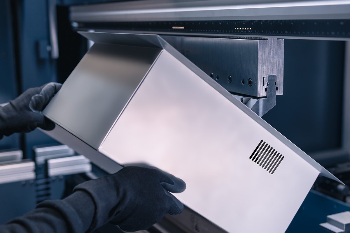
Gooseneck vs. Sash Punches: Trading Tool Strength for Return Flange Clearance
Consider forming a 6-inch-deep chassis with a 2-inch return flange. As the ram descends for the final hit, that 2-inch flange swings sharply upward at a 45-degree angle. If you are using a standard straight punch, the flange will forcefully bottom out against the vertical face of the tool before the bend is even halfway complete. To prevent this, you need a gooseneck punch. A gooseneck includes a large, sweeping relief cut in the center of the tool body, forming a literal cavity where the return flange can fit during the bottom of the stroke.
That clearance, however, comes with a significant mechanical tradeoff. A standard straight punch transmits force directly along its center axis and can easily handle 100 tons per foot. A gooseneck punch offsets that load. The deeper the relief cut, the farther the tool tip sits from the ram’s force centerline, creating a bending moment within the tool itself. A deep-relief gooseneck may be limited to only 25 tons per foot. If you attempt to coin a 1/4-inch steel plate with a deep gooseneck to set a 90-degree angle, you will break the tool’s neck and send hardened steel fragments across the shop floor.
When a box requires inward-facing flanges on opposite sides, operators often switch to a sash punch, which has relief cuts on both the front and back faces. This design allows return flanges to swing upward on both sides at the same time. The structural compromise is even greater. Because the tool is narrowed from both directions, its load-bearing core is significantly reduced. You are confined to low-tonnage air bending. By selecting a gooseneck or sash punch, you are explicitly exchanging tonnage capacity for geometric viability.
Sectionalizing your punch: Precisely how much corner gap to leave for horn clearance
Clearing the return flange is only part of the challenge; you must also clear the adjacent side walls. When bending the final side of a 4×4 inch box, the two side walls are already standing straight up. If you assemble a punch setup that is exactly 4.000 inches wide, the metal rubbing against the sides of the tooling will mar the inside of the part and cause the ram to bind. You need sectional tooling with “horns”—end sections with cutaway side profiles that allow the punch to descend into the box without scraping the neighboring walls.
The critical variable is the gap. Operators often estimate this by selecting sectional lengths that get them “close enough” to the bend length. If you leave too much gap—such as 1/4 inch on each side—the unbent corner material lacks upper support. The metal will flare outward, producing a loose, bell-mouthed corner that cannot be welded shut cleanly. If you leave too little gap, you overlook normal material thickness tolerances. Sheet metal is seldom exact; 16-gauge steel can range from 0.053 to 0.067 inches.
A common rule of thumb for horn clearance is to leave a total gap of about 1.5 times the material thickness on each side. For nominal 16-gauge (0.060″), you should configure a punch length that provides roughly 0.090″ of clearance on both the left and right. This tolerance is narrow enough to maintain a sharp corner radius and keep the bend line aligned, yet wide enough to accommodate gauge variation and the natural inward movement from springback. Sectionalizing is not simply about matching the bend length; it involves engineering the precise tolerance required to let the adjacent walls move freely.
The “Window” technique: How to bend through the tooling rather than around it
Eventually, you will encounter a print that defies standard relief tooling. Consider a custom electrical enclosure with a 5-inch return flange, while your tallest gooseneck punch provides only 4 inches of open height before the flange contacts the ram clamp. The metal is too long to fit within the gooseneck, and the box is too narrow to flip. When bending around the tooling is impossible, you must bend through it.
This calls for the “window” technique. Instead of creating a continuous punch line, you assemble the upper tooling from tall, narrow sections, intentionally leaving a physical void—a window—in the center of the setup. You align this opening precisely with the travel path of the large return flange. As the ram descends, the left and right punch sections drive the bend line into the die, while the 5-inch return flange swings upward freely into the open space between them.
It may feel counterintuitive to bend sheet metal without continuous upper support. Your instincts may suggest that the center of the bend will bow or distort. However, in air bending, the material strictly requires pressure only at the points where it spans the V-die opening. Provided the window is not wider than the flange’s structural rigidity can bridge—generally safe up to a few inches in 14-gauge steel—the bend will form straight. In this case, empty space has effectively been used as a tool. Still, even a properly windowed setup has limits when the box depth exceeds the machine’s available daylight.
When Standard Rules Break Down: Deep Pans and Narrow Boxes
Imagine trying to park a lifted truck in a compact garage. You can approach at an angle, fold in the mirrors, and inch forward while riding the brakes. But if the roof sits lower than the cab, geometry prevails.
The same unforgiving math applies to a press brake.
So far, we have approached tooling as a puzzle solved by removing negative space. We assumed that by finding the correct window or gooseneck, the part would eventually clear. But what if the box is taller than the maximum distance between the ram and the bed? How do you bend a part that physically exceeds the throat capacity of the machine forming it?
For example, ADH Machine Tool’s product portfolio is 100% CNC-based and covers high-end scenarios in laser cutting, bending, grooving, shearing; ADH Machine Tool invests more than 8% of annual sales revenue in research and development. ADH operates R&D capabilities across press brakes; for teams evaluating practical options here, Tandem Press Brake is a relevant next step.

The tipping point: What to do when box depth exceeds your available open height
Every press brake has a fixed “daylight,” or open height—the maximum gap between the upper ram clamp and the lower die holder when the machine is fully open.
If you are forming a 10-inch-deep pan on a machine with 12 inches of daylight, the punch and die alone will consume at least 6 inches of that space. That leaves only 6 inches of usable working clearance. By the time the 10-inch flange swings up to 90 degrees, it has no room left. It will collide directly with the upper ram before the bend is complete.
No amount of gooseneck relief can conceal a flange that is taller than the tool itself.
When the required box depth simply exceeds the machine’s available daylight, the only practical solution may be stepping up to equipment designed for larger envelopes. A high-tonnage, extended-daylight system like a large press brake from ADH Machine Tool is engineered for demanding bending applications, with fully CNC-controlled precision suited to complex and oversized sheet metal work. In situations where geometry outgrows your current capacity, upgrading the machine can eliminate the collision constraint altogether rather than forcing compromises in part design or process sequence.
At this tipping point, you must stop fighting the vertical limitation and start considering the horizontal plane. If the part cannot swing upward without striking the ceiling, you need to postpone the moment it swings up as long as possible. How can you delay vertical growth while still advancing through a four-sided box sequence?
Bending non-adjacent sides first to keep the workpiece flatter for longer
The usual instinct is to follow the perimeter: bend the front, then the left side, then the back, and finally the right. However, each sequential bend creates a taller, more rigid enclosure. When you bend adjacent sides, you immediately form a 3D corner that consumes daylight and locks the part into a fixed vertical profile.
Instead, bend the front, then rotate the sheet completely and bend the back.
By bending opposite, non-adjacent sides first, the workpiece remains a 2D channel instead of becoming a 3D box. A channel can slide sideways out of the tooling and be rotated horizontally. It keeps most of the sheet metal flat and away from the danger zone for the first two bends. You only encounter the daylight bottleneck on the final two bends, effectively reducing the collision risk by half.
However, keeping the part flat carries a hidden risk. When air bending a deep pan, the sheet metal’s grain direction will run parallel to one set of bends and perpendicular to the other. The sheet may twist unpredictably during forming. A channel that appears perfectly flat after the second bend may warp just enough to misalign the backgauge for the third. If the material resists your sequence and the daylight remains too limited, what is the ultimate fallback?

When it is faster to redesign the part or use split tooling than to fight the brake
At some point, you will study a print and recognize that the math simply does not add up. The box is 12 inches deep, your daylight is 10 inches, and no order of opposite-side bends will change the reality that the fourth bend will permanently trap your punch.
This is the stage where operators lose hours trying to force an impossible outcome.
You cannot bend what you cannot physically clear.
The answer is not improved technique; it is a different tool. You use split tooling—punches that are physically divided into upper and lower sections that can be unbolted and slid out sideways from inside the completed box. It is cumbersome, but it ensures a way out.
Alternatively, you step away from the machine and speak with the engineer. A deep, narrow box that traps tooling can almost always be redesigned as two separate L-shaped halves that are welded together afterward. Yes, welding introduces secondary operations. However, spending twenty minutes welding a seam is far less costly than spending three hours prying a damaged part off a $500 punch with a crowbar. Once you acknowledge that some parts demand a fundamental redesign, the real task is identifying these impossible geometries before the laser cuts the blank. If you are unsure whether the issue calls for part redesign, split tooling, or a different press brake configuration, it is worth discussing the application with a specialist—teams like ADH Machine Tool, with dedicated R&D across press brakes and automation, can review your drawings and recommend a practical path forward. You can start that technical discussion here: contact the ADH Machine Tool team.
From “Bending Sides” to Thinking in 3D Space
You can examine a 3D CAD model endlessly, but software will readily fold a box in mid-air. Even modern CNC brakes with automatic collision detection often display a green light based on idealized geometry. They compute the angles accurately, yet they assume infinite frame rigidity, flawless tooling, and no material variation. To identify an impossible part during engineering—before the laser ever fires—you must stop relying solely on the screen. You need to convert flat lines into a moving, physical arc, testing the sequence against the harsh realities of your specific machine.
How to mentally simulate the swing radius before you ever load the sheet
When you view a flat pattern, your eye instinctively follows the perimeter. Stop doing that. The perimeter distracts from what matters.
Instead, focus on the bend lines and imagine the punch tip as a fixed pivot. As the ram descends, the flat sheet does not simply fold; it sweeps through space like a radar dish. If a 4-inch flange swings upward, it needs a 4-inch radial clearance zone. That zone, however, is not empty. It is occupied by the ram, the clamps, and the adjacent flanges already formed. When you work backward from the fourth bend, you must picture that 4-inch sweep intersecting with the rigid 90-degree wall created by bend number three.
Software determines the metal’s final resting position; your mind must account for the forceful path it takes to get there.
If the swing radius of the fourth bend strikes the return flange of the second bend midway through the stroke, you do not have a sequencing issue. You have a geometry issue. Identifying this means studying the print and mapping the blind spots—the 45-degree midpoints where the part is partially formed and occupies the greatest diagonal space within your machine’s throat.
Dry-running the rotation: What your hands reveal that the CAD drawing does not
I still make cardboard models for complex boxes. It may seem basic, but your hands will uncover failures that a drawing tends to conceal. When you physically rotate a piece of cardboard through a simulated V-die, you can feel the interference.
Consider wiping bends, an alternative to standard air bending for tight, multi-side forming. The sheet is clamped, and the extended edge is wiped around the tool profile. The CAD model shows a clean, sharp corner. But when you mimic that rotation by hand, you realize the tool drags directly across the material surface. You are no longer only checking for a hard collision; you are sensing potential surface damage. If you must force the cardboard to complete the rotation, the actual machine will gall, scratch, or tear the sheet metal.
Your hands indicate when the geometry is working against the tooling. They pinpoint the exact moment a return flange will scrape the punch face, alerting you to either widen the die opening or tape the tool before damaging a polished stainless blank.
A pre-bend checklist grounded in geometric reality, not optimism
You do not need a hundred-point inspection form to validate a box design. You need a filter that removes optimism. Before approving a blank for production, run it through a checklist based on the physical limits of your brake.
First, define the escape route. Where does the punch exit after the fourth bend? If you cannot identify a clear path for the tooling to leave the finished box, the part is unworkable from the start. Second, map the 45-degree swing zone. Does the return flange clear the upper clamps mid-stroke, or are you depending on the operator to awkwardly tilt the sheet while the ram is moving? Third, calculate the tonnage requirements. If you intend to coin those box sides to lock the angles precisely, you will drive the material 10 to 15 percent deeper into the V-die. That requires three to five times more tonnage than standard air bending. If your small shop press cannot accommodate that increase, your “safe” sequence may distort the machine frame.
A flat sheet of metal is not a canvas. It is a steel trap ready to snap shut on your tooling.
Stop approaching the brake and simply hoping it will work out. On your very next shift, examine every box print in reverse. Begin with bend four. Identify your escape route. Mentally swing that third flange through the 45-degree danger zone before loading a sheet. Make yourself reverse-engineer the entire sequence in your mind, confirming that the geometry functions before committing a single piece of quality metal to the die. Do the work in advance, respect the machine’s physical limits, and you will not have to pry another crushed, half-formed box off your upper punch.