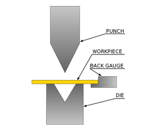
You walk up to this hundred-thousand-dollar machine, look at the ram, and see "150 TONS" stamped on the side. Your brain instantly interprets that as a massive, unstoppable hammer. You slide your metal over the V-die, stomp the foot pedal like you're crushing a bug, and wait for the machine to force the sheet into submission.
Then you hear it—a sharp, sickening pop that sounds like a gunshot.
You didn’t bend the metal. You broke it. And if that was aerospace-grade titanium instead of scrap aluminum, you just cost the shop a week’s payroll. Why did it fail when you had all that power?
Related: How Does An Electric Press Brake Work
Related: Press Brake Structure and Components
The "Big Hammer" Myth: Why Smashing Metal Destroys the Yield Point
Operating a press brake is much like driving an 18-wheeler hauling 40,000 pounds of freight down a steep mountain grade. If you simply slam the gas pedal and let gravity take over, you are not driving—you are waiting to crash. It is about controlling momentum, transferring energy smoothly through the drivetrain, and calculating your braking distance well before you reach the curve.
Scrap Bin Warning: Never try to "fix" an open angle by adding more tonnage and bottoming out the die. You will coin the metal, create stress fractures along the outside radius, and press die marks so deep that the finishing crew will want to key your car.
If raw force doesn’t produce a clean angle, what is actually happening inside the sheet?
If bending is just pushing metal into a V-groove, why do so many parts crack?
Take a piece of wire coat hanger and bend it back and forth until it snaps. Notice how hot it feels just before it breaks? That heat comes from friction as the crystalline structure tears itself apart. Metal has an elastic limit—a yield point. When you press a sheet into a V-groove, the inside of the bend compresses while the outside stretches.
If you strike it with brute force, you push past the yield point and directly into the fracture zone.
Modern fabrication relies on "air bending." We do not drive the metal all the way to the bottom of the die. Instead, we press it just deep enough into the open space of the V-groove to move it beyond its elastic limit, using only a fraction of the machine’s total tonnage. But if we are not using the die bottom as a physical stop, how do we control the final shape?
What determines whether a bend is accurate or ends up as scrap?
It comes down to exactly how far the ram travels before it stops. A difference of just four thousandths of an inch in stroke depth can shift a bend by an entire degree.
That is where the drive mechanism comes into play. Whether the machine uses hydraulic cylinders linked by a torsion bar or an electric servo motor driving a belt, the drive’s sole purpose is to deliver energy with microscopic stopping precision. If a hydraulic system becomes even slightly unbalanced between the left and right cylinders under load, one side of the part will overbend while the other springs back.
You are not a blacksmith swinging a hammer. You are a conductor controlling an energy-delivery system. The machine supplies the force, but the drive mechanism determines exactly when and how that force stops.
So what happens when different drive systems try to reach those microscopic stopping points under pressure?

What’s actually happening during a bend (controlled force, not impact)
Think about folding a heavy-duty corrugated pizza box. If you simply slam your fist into the middle, you crush the flutes and destroy the structure. Instead, you press your thumbs along the scored line, applying just enough force until the cardboard yields and folds. Metal behaves the same way, only at a molecular scale. When the ram descends, the drive mechanism is not fighting the entire sheet at once. Up to 80% of the permanent deformation in sheet metal occurs before the punch penetrates even 30% into the die opening. The metal is not waiting to hit the bottom of the die to take shape; it is yielding in mid-air.
Why does it yield at that point, and why doesn’t the entire sheet simply snap in half?
Where does the metal actually yield—and why doesn’t it snap?
Look closely at the edge of a freshly bent piece of 1/4-inch steel. The outside radius appears slightly porous, as if stretched, while the inside radius looks densely packed. When the punch tip pushes the sheet into the V-die, the metal does not bend uniformly. The fibers on the outside of the curve are pulled apart, while the fibers on the inside are compressed together. Between them lies the neutral axis—a microscopic line where the metal experiences no strain at all.
To achieve a permanent angle, the outer and inner fibers must be pushed beyond their elastic limit—where they want to spring back—and into the plastic zone, where the deformation remains. But the ram must stop before the material reaches its ultimate tensile strength. If the drive mechanism pushes even a fraction of an inch too far, those outer fibers will tear.
Scrap bin warning: Never ignore the grain direction of sheet metal. If you bend parallel to the rolling grain—like splitting firewood along the grain—the stretched outer fibers can fracture long before you reach the programmed angle. Always bend across the grain.
If we are simply floating the metal in the die to reach the plastic zone, do we ever actually need to hit the bottom?
Air bending vs. bottoming: Does the metal really need to touch the bottom of the die?

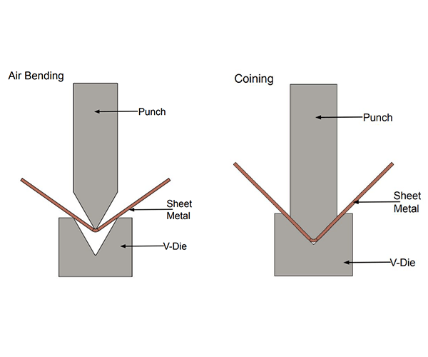
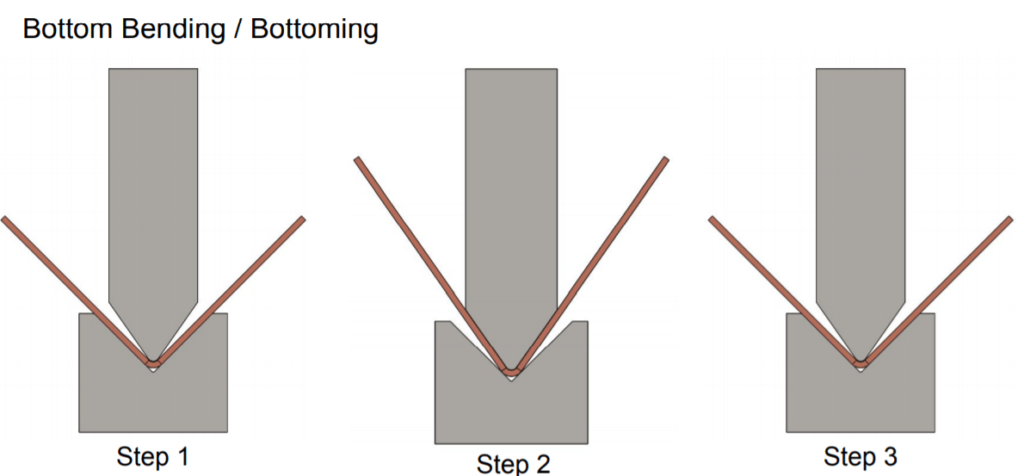
Take a 90-degree punch and a matching 90-degree die. If you force the sheet metal all the way down until it is clamped between the two tools, you are "bottoming." For decades, this was the only way to achieve an accurate angle because older mechanical press brakes could not stop mid-stroke with precision. Bottoming forces the metal to conform exactly to the shape of the tooling. It guarantees the angle, but it requires very high tonnage and increases tool wear by three to five times due to the intense localized stress at the punch tip.
We rarely do this anymore.
Today, we use "air bending." The die acts only as a bridge, and the punch pushes the metal into the open space between the V-shoulders. The final angle is determined entirely by how far the punch travels. Stop a millimeter higher and you get a 120-degree bend. Push a millimeter deeper and you get an 80-degree bend. The metal never contacts the bottom of the V-groove.
But if the metal is stretching and compressing in mid-air, what happens to the overall size of the part?
The bend allowance problem: Why your flat pattern never matches your finished part
Take a flat piece of aluminum that is exactly 10 inches long and bend it perfectly in half. Measure the two legs. They will not be 5 inches each. They might measure 5.06 inches.
Remember the neutral axis we discussed earlier? When metal bends, the stretching on the outside radius is always slightly greater than the compression on the inside. The entire piece physically elongates. This growth is called the "bend allowance," and it varies based on material thickness, the inside bend radius, and the specific V-die opening used. If you do not account for this stretch before cutting your flat blank, your final flanges will be out of tolerance and your mounting holes will not align.
Bending metal does not just change its shape; it changes its total surface area.
An engineer can calculate that stretch precisely on a computer, but the math only works if the machine stops exactly where it should. So how do the actual gears, fluids, and motors of a press brake turn that perfect math into physical reality under fifty tons of pressure?
If you want to see how modern CNC press brakes translate calculated bend allowance into repeatable, real‑world accuracy, you can review the detailed technical brochures from ADH Machine Tool, including machine configurations, control systems, and application ranges for high‑end bending and sheet metal automation systems. Download the full specifications here: press brake brochures and technical documents.
Four Drive Systems, Four Completely Different Machines
Running a press brake is much like driving an 18‑wheeler hauling 40,000 pounds down a steep mountain grade. You do not simply stomp on the gas and hope for the best. You must manage momentum, calculate braking distance, and steer through curves, using the transmission to control how energy is transferred. The machine supplies the raw power, but the drive system—the gears, fluids, or motors above the ram—functions as that transmission. It determines exactly how power is delivered to the sheet metal. As established, modern air bending requires stopping the punch in mid‑air with accuracy measured in thousandths of an inch. If the machine cannot stop precisely, the angle will be wrong, the part will stretch out of tolerance, and the flat‑pattern calculations become useless.
So what happens when your machine’s “transmission” is nothing more than a massive, spinning wheel of solid iron?
The Mechanical Press Brake Trap: Why the flywheel effect makes it physically impossible to stop mid‑stroke
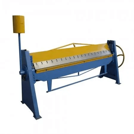
Look at the side of a traditional mechanical press brake and you will see a 500‑pound cast‑iron flywheel spinning continuously at 400 RPM. An electric motor keeps the wheel turning, storing a large reserve of kinetic energy. When you step on the foot pedal, a clutch engages and physically locks the spinning flywheel to a crank mechanism that drives the ram downward. Once the clutch engages, the ram is fully committed. It will travel to the absolute bottom of its mechanical stroke, dead center, before returning upward. You cannot feather the pedal to stop it halfway. You cannot ease into the material. The machine releases 100% of its stored kinetic energy into the tooling in a fraction of a second.
Scrap Bin Warning: Never attempt to air bend on a purely mechanical brake by shimming dies or guessing stroke depth. If the tooling is set even a fraction of an inch too high, the runaway ram will not stall—it will violently shatter the punch, explode the V‑die into shrapnel, and potentially crack the machine’s side frames.
Because they cannot stop mid‑stroke, mechanical brakes require bottoming the metal against the die to achieve the desired angle. They are fast and well suited for punching holes or high‑volume, low‑variation stamping, where the ram must hit the same physical bottom every time. For modern precision air bending, however, they are a liability.
If mechanical brakes are runaway trains, how do we get a machine that actually allows us to apply the brakes?

The Hydraulic Workhorse: Why fluid power forgives beginner mistakes but limits speed
Pump 50 gallons of hydraulic oil through a proportional steel valve at 3,000 PSI and you gain full control over the ram. Instead of a spinning flywheel, hydraulic press brakes use electric motors to pressurize oil and force it into large cylinders on either side of the machine. Because liquids do not compress, the pressurized oil delivers immense, steady force. When you release the foot pedal, the valves snap shut, oil flow stops, and the ram halts immediately. This fluid control makes air bending possible. You can inch the ram downward, check the angle, and adjust depth on the fly without destroying the tooling.
But hydraulic fluid has a hidden weakness: it heats up.
As oil is pushed through valves hour after hour, friction generates heat. As hydraulic oil heats up, its viscosity decreases and it becomes thinner. A valve that sealed perfectly at 8:00 AM may allow a microscopic amount of thin oil to leak past by 3:00 PM. That small leak can cause the ram to drift a few thousandths of an inch deeper into the die, turning precise 90‑degree bends into 88‑degree rejects by the end of the shift. Modern manufacturers address this with hybrid systems—using small servo motors to drive hydraulic pumps directly, reducing energy consumption and heat—but the system remains subject to the limits of fluid dynamics.
If oil temperature compromises our microscopic tolerances, how can we remove the fluid from the system altogether?
Servo-Electric Systems: Trading raw tonnage for absolute repeatability and direct control
Remove the oil tanks, hoses, and hydraulic cylinders. Replace them with twin AC servo motors that drive heavy-duty ball screws or Kevlar belts. A servo-electric brake monitors the ram’s position up to 1,000 times per second. When the computer commands the motor to stop the punch at exactly 2.145 inches into the die, it stops at 2.145 inches. There is no fluid to heat up, no valves to leak, and no flywheel to overrun. The result is absolute, precise repeatability. If you bend a part on Monday morning, you can bend the identical part on Friday afternoon and the angle will not vary by a single degree.
The compromise is raw force. While hydraulic systems can readily scale to deliver 1,000 tons of force for bending thick steel plate, servo-electric systems typically top out around 300 tons before their mechanical linkages become impractically large. They are designed for high-speed, high-precision work on thinner gauges, where accuracy determines profitability.
If servos provide precision and hydraulics provide heavy force, why would anyone connect an air compressor to a press brake?
Pneumatic Press Brakes: Where do they actually make sense on the shop floor?
Disconnect a shop air hose operating at 120 PSI and attach it to a small benchtop press brake cylinder. Unlike hydraulic oil, air is highly compressible and behaves like a spring. When the punch contacts the metal, the air inside the cylinder compresses before the ram fully drives into the material. This makes the ram feel spongy and less predictable under heavy loads, which is precisely why you will not find a pneumatic drive on a 100-ton machine bending structural steel.
If you want a deeper, step‑by‑step look at the mechanics behind this behavior—how air compression, valve timing, and frame rigidity interact in real machines—this breakdown on how pneumatic press brakes work adds useful context. It reflects the same engineering perspective ADH Machine Tool applies across its bending equipment, where understanding force transmission and structural stiffness is critical to choosing the right drive system.
However, pneumatics dominate a specific segment of the shop. If you are forming 20-gauge aluminum brackets for HVAC ducts or light electronics enclosures, you do not require 100 tons of force. You need a fast, economical, clean machine that does not leak oil and can cycle quickly. A 15-ton pneumatic brake provides exactly that. It illustrates a fundamental shop-floor principle: the drive system must match the material being formed.
But whether you are operating a spongy 15-ton pneumatic or a rigid 500-ton hydraulic, knowing the drive type will not protect you if you demand more than the machine’s frame can withstand. How do you determine the exact force your metal will resist with before you ever press the pedal?
The Tonnage Equation: Calculating the Force Before You Touch the Pedal
Bending a heavy steel plate is similar to trying to snap a solid ash baseball bat over your knee. If you do not calculate in advance how much resistance that dense wood will provide before you pull down, you will not break the bat—you will break your kneecap. The same physical principle applies to a press brake. You can have the most advanced, perfectly matched servo-electric drive system available, but if you demand more force than the metal’s yield point allows, that kinetic energy must be absorbed somewhere. It will transfer directly back into the machine’s frame, the tooling, and ultimately, you. To prevent this dangerous transfer of energy, you must calculate the exact force your metal will resist with before you ever press the pedal.
If you are unsure how to translate these tonnage calculations into the right machine configuration, it is worth discussing your application with a manufacturer that can validate the numbers against real engineering data. ADH Machine Tool invests more than 8% of its annual revenue in research and development across press brakes, laser cutting, and intelligent equipment, and supports customers in over 100 countries. You can contact the ADH Machine Tool team to request an application evaluation, quotation, or technical consultation before committing to a specific tonnage or drive type.

How does material thickness exponentially change the required machine power?
If you double the thickness of a sheet of metal, you do not double the required tonnage; you increase it fourfold.
Tonnage requirements rise with the square of the material thickness. When you bend 1/8-inch mild steel, you stretch a certain number of molecular bonds on the outside radius and compress the same number on the inside radius. Moving up to 1/4-inch steel does not merely add more material. It increases the distance from the neutral axis—the invisible center line within the metal that neither stretches nor compresses—to the outer surfaces. As a result, the outer fibers must stretch much farther and the inner fibers must compress much harder to reach the same angle. This geometric fact means structural resistance escalates dramatically as thickness increases.
Given that ADH Machine Tool's product portfolio is 100% CNC-based and covers high-end scenarios in laser cutting, bending, grooving, shearing, for teams evaluating practical options here, Large Press Brake is a relevant next step.
The machine is indifferent to intuition and responds only to mathematics.
If you treat a 1/4-inch plate as if it were two stacked pieces of 1/8-inch plate, you risk stalling hydraulic pumps, burning out servo motors, or physically bowing the ram of a mechanical brake. The required force must be calculated and compared against the machine’s absolute capacity before any part is loaded. If thickness multiplies force so aggressively, what happens when it is combined with the specific tooling you have selected?
Material thickness, die width, tensile strength—which variable bites first?
Coining metal requires three to five times the tonnage needed for air bending.
Although thickness sets the baseline calculation, the bending method and tooling introduce a major multiplier. In air bending, the metal is pressed into a V-die, using the die edges as leverage points. Increasing the V-die width increases leverage and sharply reduces the required tonnage. By contrast, when you attempt to coin the metal—crushing it an additional 10 to 15 percent into the bottom of the die to permanently set the angle—you eliminate that leverage. The process shifts from bending to forging. This is where modern electric press brakes alter the equation. Their direct-drive torque motors provide such precise positional control that they can achieve the same accurate, zero-springback angles through controlled air bending, using only a fraction of the peak force demanded by coining.
Finesse scales more effectively than brute force.
If you disregard the advantages of air bending and insist on coining thick stainless steel solely to achieve an angle, the material’s tensile strength becomes a critical obstacle. Stainless steel typically requires about 50 percent more tonnage than mild steel, and when that is multiplied by a fivefold coining factor, the demanded force becomes extreme. What happens to the machine when that finesse is ignored and the raw power is miscalculated?
For operations that routinely face this level of load, the solution is not guesswork—it is engineered capacity and synchronized control. A CNC-driven tandem configuration allows two machines to operate as one, distributing extreme tonnage evenly across long workpieces while maintaining positional accuracy. Solutions such as the tandem press brake from ADH Machine Tool are designed for high-demand bending scenarios where thickness, tensile strength, and part length would overwhelm a single frame, combining scalable force with the precision control modern sheet metal production requires.
What happens to the tooling—and the operator—when you overestimate the required tonnage?
Early hydraulic press brakes relied on large outboard cylinders mounted at the far left and right of the ram, creating a problem known as “crowning.”
When tonnage is pushed to the limit on difficult material, the force does not disappear into the steel; it is transferred back into the machine. In older outboard-cylinder designs, applying 200 tons at the ends of the ram caused the center of the heavy steel bed to bow downward under stress. The result was a precise 90-degree bend at the ends of the part and a loose, 94-degree, canoe-shaped bend in the middle because the punch could not penetrate as deeply where the bed deflected. Modern up-acting designs moved the cylinders inward to reduce this effect, but the underlying physical principle remains unchanged: force deforms steel.
Scrap Bin Warning: Never try to coin heavy-gauge stainless steel on a light-duty brake simply because the part fits inside the die. If you misjudge the tonnage multiplier and bottom out 1/4-inch stainless, the extreme pressure can split your hardened steel V-die completely in half, sending shrapnel across the shop floor at bullet-like speed.
You can calculate the tonnage precisely, distribute the force evenly across the ram, and keep the machine fully rigid. But the moment you lift the punch out of the V-die, the metal remembers its original state and will actively attempt to unbend itself.

The Springback Factor: Why Perfect Tonnage Does Not Ensure a Perfect Angle
Operating a press brake is similar to driving an 18-wheeler hauling 40,000 pounds of freight down a steep mountain grade. You cannot simply press the accelerator blindly and expect the brakes to rescue you at the bottom. You must manage your momentum through the drive type, calculate your precise braking distance based on the tonnage, and carefully steer through the curves created by the material's natural resistance. You may deliver exactly the right amount of energy to the steel, but the steel still has a say. Every piece of metal retains a memory, and it will always attempt to return to flat as soon as you raise that ram.
If the machine and material are perfectly matched, why does the metal still relax out of tolerance?
Consider bending a thick plastic ruler over the edge of your workbench. Pull it down to exactly 90 degrees, release it, and it springs back to 110. To make it stay at 90, you have to push it down to 85. Steel is essentially a very stiff ruler. When you push metal beyond its yield point, you permanently change its molecular structure, but the inner core of the bend remains elastic. That elastic core behaves like a tightly wound spring under load.
It seeks to return to its previous shape.
This is why 99 percent of modern air-bending applications use 85-degree or 88-degree tooling to produce a 90-degree bend. You must intentionally overbend the material, driving the punch deeper into the V-die so the metal can spring back into the desired tolerance. However, springback is a variable factor. It increases directly with the tensile strength of the steel and the width of the die, which makes textbook tonnage calculations ineffective if you fail to account for the material’s elastic limits.
Scrap Bin Warning: Never assume the springback on a large-radius bend will match that of your standard sharp bends. If you depend on basic textbook calculators for a large-radius bend without running test pieces, the metal’s unpredictable elastic zone can shift your angle by five degrees, turning an entire run of expensive high-strength steel into scrap.

How does a CNC backgauge convert raw force into repeatability across multiple parts?
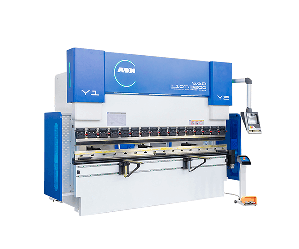
Overbending is effective only if you strike the exact same location on the metal every time. If your bend line shifts by even the thickness of a human hair, your mechanical advantage changes, and your springback calculation becomes invalid. This is where the CNC backgauge comes into play. It functions as the transmission of your precision energy‑delivery system, ensuring force is applied exactly where intended—something best achieved when the backgauge, controls, and frame are engineered as a single CNC system. Modern solutions like a fully integrated CNC press brake from ADH Machine Tool are designed around this principle, pairing CNC-driven positioning with repeatable control so precision at the backgauge translates directly into consistent angles across every part.
It governs the geometry of the strike.
Rather than depending on an operator with a tape measure and chalk, a multi-axis CNC backgauge uses servo motors to position the mechanical stops behind the die with extremely high precision. When the sheet metal is slid against these fingers, the machine knows exactly where the neutral axis is located over the V-die. By fixing the physical position of the part, the CNC removes springback as a variable. This allows the computer to adjust the ram stroke depth in real time, compensating for the metal’s memory using sensor feedback instead of operator judgment.
CNC crowning vs. manual shimming: which wins the final battle against metal memory?
Even with precise backgauge positioning and accurate overbending, you still have to contend with the physical behavior of the machine itself. As heavy tonnage is applied, the center of the press brake bed bows downward. This deflection means the punch penetrates less deeply in the middle of the part, resulting in less overbend and therefore more springback at the center than at the ends.
The metal remembers, and the machine bends.
In the past, this was addressed with manual shimming. Operators would cut strips of cardboard or metal shim stock and place them under the center of the bottom die to raise it, relying on trial and error to achieve a straight bend. It was a skill, but it was slow and highly inconsistent. Modern press brakes now use CNC crowning tables, which are motorized wedges built into the machine bed. As the ram descends, the CNC calculates the required compensation based on tonnage and automatically drives the wedges together, bowing the bed upward to match the ram’s downward deflection. The result is a uniform stroke depth across the entire length, addressing both machine deflection and metal memory in a single, continuous process. With control over energy and springback established, the next step is determining which machine is right for your shop.