Why Your K-Factor Is Misleading You: Practical Solutions for Accurate Bend Allowance and Bend Deduction

Factory-sale Equipment
We have over 20 years in manufacturing. 
Press Brake
Laser Cutting Machine
Panel Bender
Hydraulic Shear
Get FREE Quote
Publish Date: March 11, 2026

You can carry the trigonometry out to five decimal places. You can model exact corner reliefs, compute precise bend deductions, and export a pristine DXF. But if you began with a 0.44 K-factor pulled from a drop-down menu or a dog-eared 1998 machinery handbook, you’re not engineering a part—you’re calculating your scrap rate with remarkable accuracy.

I’ve watched thousands of dollars’ worth of perfectly laser-cut sheet metal end up in the recycling bin because an engineer trusted the default settings. The math was impeccable. The assumptions were worthless.

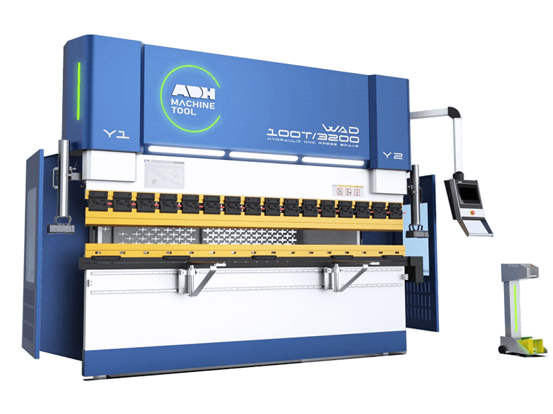
In modern fabrication environments powered by high-precision equipment such as a CNC Press Brake, repeatability is no longer the weak link. The real variable is whether your bend calculations reflect the actual material behavior and tooling setup on the shop floor.

Your Flat Patterns Aren’t Failing Because of Bad Math — They’re Failing Because of Bad Assumptions

Where the “Industry Standard” 0.33–0.50 K-Factor Originated (and Why It’s a Trap)

Open your CAD software and insert a sheet metal part. The default K-factor is almost certainly 0.44. That number is a relic—a historical compromise for low-carbon A36 steel bent over a conventional V-die, fossilized into software defaults decades ago.

Now hand that flat pattern to an operator bending soft 5052 aluminum with an inside radius-to-thickness ratio under 1. Soft aluminum compresses readily; under load, its neutral axis shifts dramatically inward. The real K-factor for that setup is closer to 0.33. That 0.11 gap isn’t a rounding discrepancy—it’s the difference between a part that drops into the assembly fixture and one that goes straight to scrap. The handbook offers a broad “safe” range of 0.33 to 0.50, and CAD software conveniently splits the difference—virtually guaranteeing you’re never precisely right.

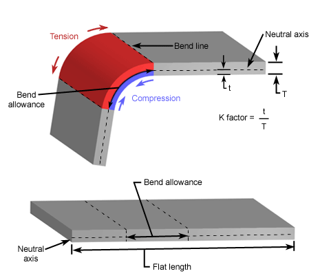
Textbook Formula -> K = t / T (distance to the neutral axis divided by material thickness). Shop Floor Translation -> K = The exact point where the metal transitions from compression to tearing—and that point shifts the moment the operator swaps a 1/2" V-die for a 3/4" V-die.

If you are programming bends on a modern CNC Press Brake, remember: the controller can repeat angles with extreme precision—but it cannot rescue a flat pattern built on the wrong K-factor.

The Hidden Conflict: Textbook Neutral Axis Theory vs. Shop-Floor Reality

A 1/2" V-die will produce a completely different flat pattern than a 3/4" V-die on the exact same piece of 14-gauge steel.

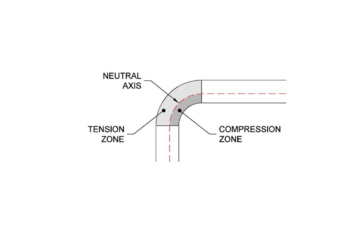
Textbook theory treats the neutral axis—the imaginary plane within a material that experiences neither compression nor tension—as an intrinsic property of the metal itself. It isn’t. On the shop floor, the neutral axis is forced into position by the tooling. When you air-bend over a wider V-die, the bend radius increases naturally, and the neutral axis shifts closer to the inside surface, driving the K-factor down toward 0.33. Push that same material into a tighter die, and the neutral axis is forced back toward the center, sending the K-factor climbing toward 0.50.

In large-format fabrication—especially when synchronizing two machines in a Tandem Press Brake configuration—this tooling influence becomes even more critical. A minor die-width variation across long workpieces can amplify dimensional drift over multiple bends.

You are modeling a fixed material constant. The press brake operator is executing a dynamic physical event. When your CAD system assumes a static K-factor, it collides with the realities of air bending on the shop floor. You end up designing for a theoretical version of the metal—one that doesn’t exist in practice.

V-DIE WIDTH VS. FLAT PATTERN

What a 0.010” Deviation per Bend Really Costs in a Multi-Bend Sequence

I once watched a junior engineer agonize over a five-bend power supply chassis that ended up a full eighth of an inch oversized at the final flange. He had checked the first bend straight off the brake—it was off by just 0.010" (ten thousandths). In machining, you might chase that tolerance. In sheet metal, ten thou can feel like noise.

But sheet metal bending is sequential. That 0.010" error in the first bend shifts the backgauge reference for the second. The second bend introduces its own 0.010" deviation, compounding the first. By the time the operator reaches bend five, the hole pattern for the mating lid is misaligned by 0.050", and the overall length is out of spec.

The scrap bin is the most ruthless auditor of an engineer’s calculations. It doesn’t care how elegant your trigonometry looks if it rests on a flawed assumption. An operator might try to “cheat” the backgauge to preserve the hole locations, but then the overall flange dimension suffers. You can’t compensate for a bad premise with better math.

The Physics Behind the Shift: Why the Neutral Axis Keeps Moving

Tensile Strain, Compressive Stress, and the Layer in Between

In Mechanics of Materials, you learn that for an ideal, straight I-beam under pure bending, the neutral axis lies precisely at the geometric centroid. It carries zero stress. Material near this axis contributes almost nothing to load resistance, which is why structural engineers concentrate mass in the flanges and keep the web thin. It is a clean, elegant mathematical truth.

It is also almost entirely irrelevant on the shop floor.

Sheet metal air bending is not pure elastic bending—it is intense, highly localized plastic deformation. As the punch drives the sheet into the V-die, the outer fibers elongate and thin, while the inner fibers are forced into compression against the punch tip. Because steel and aluminum resist compression far more effectively than tension, the zero-stress layer cannot remain at the geometric center. To balance these extreme forces, the neutral axis physically shifts inward.

Textbook Formula -> Neutral Axis = Centroid (y = 0) in pure elastic bending.

Shop Floor Translation -> Neutral Axis = The precise depth where the material’s resistance to being crushed outweighs its tendency to stretch.

Bend Deduction

How the Inner Radius-to-Thickness Ratio Controls the Shift

Bend a piece of 0.120" (11-gauge) steel with a punch that has a 0.060" tip radius. Your inside radius-to-thickness (Ir/t) ratio is exactly 0.5. At ratios this tight, compressive forces on the inside of the bend become extreme. The material has nowhere to displace. It bulges laterally, driving the neutral axis sharply toward the inside surface and pulling the K-factor down toward 0.33.

Now open the die and switch to a punch with a 0.250" radius.

Your Ir/t ratio is now greater than 2.0. The stresses distribute more evenly through the material thickness. Inner-surface compression is less severe, allowing the neutral axis to migrate back toward the center of the sheet and pushing the K-factor closer to the theoretical 0.50.

Material thickness and inner radius cannot be treated independently—they function as a locked pair that ultimately determines where the neutral axis will stabilize.

Textbook Formula -> K-factor = log(min(100, max(1, Ir/t))) (or similar empirical approximations).

Shop Floor Translation -> K-factor = A sliding scale determined entirely by how tightly the inner radius is constrained relative to the material thickness.

The Sharp Bend Exception: How Air Bending Dynamics Shatter Textbook K-Factors

I once watched a fabricator dump an entire pallet of 1/4" A36 steel brackets into the scrap bin because an engineer specified a 0.030" inside radius on the drawing. You cannot force a 0.030" radius into 0.250" plate with an air bend. The material will simply refuse to form a radius tighter than roughly 63% of its thickness—a limit known as a sharp bend.

Push beyond that limit and the punch tip stops forming a smooth radius and starts cutting a groove. It coins the center of the bend, producing a parabolic inner profile instead of a true arc. The neutral axis effectively fractures and shifts unpredictably because the inner fibers aren’t just compressing—they’re being mechanically displaced. Your CAD model assumes a clean, tangential arc. The press brake produces a crushed, work-hardened V-shape. The resulting flat pattern will be dramatically undersized.

Textbook Formula -> Inside Radius = Punch Tip Radius.
Shop Floor Translation -> Inside Radius = The natural radius the material forms as it spans the V-die opening—regardless of how sharp the punch tip is.

Grain Direction and Ductility: The Hidden Variables That Distort the Math

Take two blanks of 16-gauge 304 stainless steel cut from the same sheet and bend them over the same die. Bend one parallel to the rolling direction and the other perpendicular. The parallel bend will require higher tonnage, form a slightly different inside radius, and likely show micro-cracking along the outer surface. The perpendicular bend will form cleanly and with less resistance.

The grain structure formed at the steel mill behaves much like the grain in wood. Bend with the grain, and you’re pulling those longitudinal fibers apart—inviting premature cracking on the outer surface and driving the neutral axis deeper into the material to compensate. Bend across the grain, and the fibers elongate more evenly, producing a smoother, more predictable result.

Ductility plays the same subtle but decisive role. Dead-soft 5052-H32 aluminum compresses readily, pushing the neutral axis inward. High-strength, rigid steel resists compression, keeping the axis closer to the centerline. If your flat-pattern calculation assumes the material is isotropic—that it performs the same in every direction—you’re building your design on a false premise.

Textbook Formula -> Yield Strength = A fixed value (pulled from the material spec sheet).
Shop Floor Translation -> Yield Strength = A directional variable that changes based on how the laser nests the part on the sheet.

Two Logics, Two Workflows: Additive Bend Allowance vs. Subtractive Bend Deduction

The Exact Formulas: What Each Variable Really Measures

Suppose you need to fabricate a simple U-channel: a 6-inch base with two 2-inch flanges, formed from 0.120" cold-rolled steel. The moment you calculate the required flat blank, you arrive at a crossroads. You can either construct the answer by adding up each component of the formed shape, or you can begin with the finished outside dimensions and subtract what the bending process consumes.

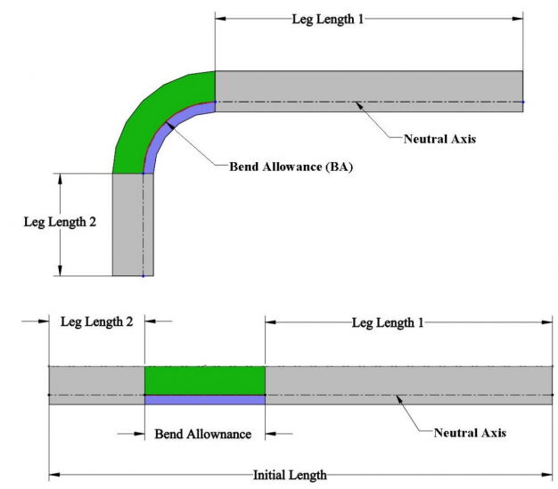
Bend Allowance (BA) follows the additive logic. It treats the part as three straight, flat legs joined by two curved sections. To determine the blank length, you add the straight length of Flange 1, the arc length of the first bend, the straight length of the Base, the arc length of the second bend, and finally the straight length of Flange 2.

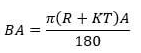
Textbook Formula -> BA = (π/180) × Bend Angle × (Inside Radius + (K-factor × Thickness))
Shop Floor Translation -> BA = The true length of the neutral axis—if you could somehow peel it out of the bend and lay it perfectly flat on a workbench.

Bend Deduction (BD) takes the subtractive approach. It completely ignores the internal arc. Instead, it evaluates the part the same way a quality control inspector does: with a pair of calipers. The inspector measures a 2-inch flange, a 6-inch base, and another 2-inch flange—for a total of 10 inches in outside linear dimensions. However, because the material stretches and effectively "cuts the corner" during forming, the required flat blank must be shorter than 10 inches. Bend Deduction represents the total amount of material that disappears in the forming process. You simply add up the outside dimensions and subtract one deduction value for each bend.

Flat Blank Calculation

The Outside Setback Calculation: Where Most CAD Users Make Their First Mistake

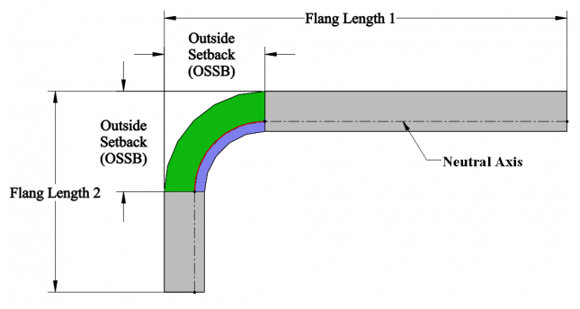
To understand why these two workflows produce dramatically different shop-floor results, you have to consider where the calipers actually contact the metal. When you measure that 2-inch flange, your calipers hook onto the sheet edge and extend down to the bottom of the bend. But the bottom of the bend is a radius. In reality, your calipers are referencing a sharp theoretical intersection in space—the point where the two outside planes of the metal would meet if the corner were perfectly square.

That floating point in space is known as the virtual sharp apex. The distance from the beginning of the physical bend radius to this imaginary apex is called the Outside Setback (OSSB).

Textbook Formula -> OSSB = tan(Bend Angle / 2) × (Thickness + Inside Radius)
Shop Floor Translation -> OSSB = The phantom distance your calipers register—even though no steel actually occupies it.

When you use Bend Deduction, the OSSB is already embedded in your total outside dimensions—you don’t have to think about it. But with Bend Allowance, you must calculate the precise length of each straight leg before the bend begins. That requires taking the 2-inch outside dimension and subtracting the OSSB. This is where the trap closes. If your CAD software assumes a 0.030" inside radius, it computes a very small OSSB. If the press brake operator actually forms the part with a V-die that produces a 0.090" inside radius, the real-world OSSB is significantly larger. Your straight-leg calculation is now mathematically flawed before the punch ever contacts the metal.

Why Additive BA Logic Forces a Conversion Step That Compounds Tolerance Error

I once had to scrap a $3,000 production run of 5052 aluminum chassis enclosures because a junior engineer insisted on generating the flat patterns using Bend Allowance. He modeled the part with a fixed K-factor and a theoretical inside radius, calculated the straight legs, added the allowances, and sent the DXF to the laser. When the operator formed the first chassis, the overall dimensions came up nearly forty thousandths of an inch short—per bend.

The engineer blamed the operator. The operator blamed the engineer. The real problem was the additive math.

When you rely on Bend Allowance, you’re doing math on abstractions. The formula demands that you perfectly predict the actual inside radius to calculate the OSSB, subtract that OSSB to determine a theoretical straight leg, and then add a theoretical arc length back in. Every time you convert an outer dimension to a straight leg—and then convert it back—you introduce rounding error and a radius assumption. If the material is even slightly harder than expected and forms a larger radius, your OSSB shifts, your straight leg shifts, and your BA shifts with it. The inaccuracies stack up across every flange.

Bend Deduction contains the error instead of amplifying it. Add the outside caliper dimensions (2" + 6" + 2" = 10") and subtract the empirical Bend Deduction taken directly from a test bend, and you eliminate the OSSB conversion entirely. It doesn’t matter where the straight leg ends and the arc begins. All that matters is the total material consumed between the two outside planes.

Managing Angles Greater Than 90 Degrees Without Breaking the Trigonometry

This mathematical split turns into a full-blown problem once you bend beyond a standard right angle. Take a sheet to a 120-degree bend angle (a 60-degree included angle), and the geometry quickly becomes unforgiving.

At 90 degrees, the tangent of half the bend angle is exactly 1, so your OSSB equals the material thickness plus the inside radius. At 120 degrees, however, the tangent multiplier jumps to 1.732. With such an acute bend, the virtual sharp apex is driven dramatically outward into empty space. Your calipers are effectively measuring to a point suspended well beyond the physical edge of the metal.

If you try to apply Bend Allowance here, the math quickly turns absurd. The OSSB grows so large that subtracting it from the outside dimension to calculate the straight leg often yields a negative value. Now your CAD system is attempting to combine a negative straight segment with a positive arc length. It takes layers of conditional logic just to prevent the model from breaking.

Subtractive Bend Deduction, by contrast, remains stable. As the virtual apex shifts outward and the outside dimension increases, the empirical deduction value scales proportionally, cleanly subtracting the excess. No mathematical gymnastics required.

The Structural Divide: Why Bend Deduction Prevails in CNC Production

Engineers Dimension from Exterior Edges—Not Theoretical Arc Centers

Press Brake Bending

I once scrapped $1,200 worth of 304 stainless brackets because an engineer chose to dimension the entire drawing to the inside tangent lines of the bend radii. His goal was to simplify his Bend Allowance calculations. Now hand that flat pattern to an operator forming soft 5052 aluminum with an inside radius-to-thickness ratio under 1. Ask him to measure an invisible inside tangent line with calipers—and watch how fast he laughs you out of the shop.

Engineers design to outside envelopes. SolidWorks defaults to outside dimensions. Inspectors verify outside dimensions. When you pull a 6-inch base with 2-inch flanges off the brake, your calipers reference the physical exterior edges—not the inside arc.

The divide between Bend Allowance and Bend Deduction ultimately comes down to alignment: Is your CAD system calculating the flat pattern from dimensions you can physically measure, or from ones that exist only in theory? Bend Deduction wins because it starts with the 10 inches of outside material you can actually measure and subtracts the elongation introduced by bending.

If the Press Brake References Outside Dimensions, Why Are We Adding Inside Lengths?

The disconnect becomes even more obvious when you examine how the machine operates. A modern CNC press brake controller positions the backgauge using the outside flange dimension. The backgauge fingers physically register against the outside edge of the sheared blank.

Textbook Formula -> Bend Allowance = The arc length of the neutral axis between the bend tangent lines.
Shop Floor Translation -> Bend Allowance = A phantom dimension you can’t touch, measure, or reference against a backgauge.

If the machine references the outside edge, and quality control verifies the outside edge, then building a flat pattern by summing inside dimensions is a built-in contradiction. You’re forcing the CNC controller to convert your inside-out calculations back into outside-in reality. Every handoff introduces risk—rounding errors, incorrect radius assumptions, or mismatched tooling data can scrap the part. Bend Deduction eliminates that translation step altogether. It speaks the press brake’s native language.

Containing vs. Compounding Error: Tracking Tolerance Stack-Up Across Sequential Bends

When your CAD model assumes a fixed K-factor, it fundamentally conflicts with the variable nature of real-world air bending. Consider a four-bend U-channel. Using Bend Allowance, an error in the assumed inside radius alters your straight-leg calculation. That miscalculation shifts the physical starting point of the second bend. By the fourth bend, your hole pattern can be off by an eighth of an inch. Additive logic doesn’t absorb error—it amplifies it across every downstream feature.

Bend Deduction contains the error within the bend itself—but only if it’s applied correctly. In multi-bend parts, deductions must be split evenly between adjacent legs. If the total deduction is 0.127", subtract 0.0635" from the flange and 0.0635" from the base. If you fail to split it, the overall flat length may appear correct, yet critical downstream features will drift out of position. When properly divided, Bend Deduction prevents an incorrect radius assumption from corrupting the baseline straight-leg dimensions of the entire part.

Is There Ever a Legitimate Fabrication Use Case for Bend Allowance?

Yes—but rarely in precision sheet metal chassis fabrication. Bend Allowance relies on additive logic driven by internal dimensions. That approach makes sense when designing flat patterns from first principles for custom rolled cones, or in progressive die stamping where material flow follows the internal neutral axis. If you’re reverse-engineering a rolled cylinder and the external envelope is irrelevant, Bend Allowance helps ensure you don’t cut your blanks too short.

But if you’re working with 0.063" aluminum and need to hold a ±0.005" tolerance on a multi-flange chassis, Bend Allowance becomes a liability. It relies on a theoretical neutral axis to define a part that will ultimately be evaluated by its physical exterior dimensions. We’ve already established that Bend Deduction’s subtractive approach aligns structurally with CNC production—but its accuracy still hinges entirely on supplying a flawless, empirically derived K-factor.

Stop Guessing the Neutral Axis: How to Empirically Determine Your True K-Factor

A new supplier delivers a skid of 0.090" 5052-H32 aluminum. On paper, it matches your specified material exactly. But if you apply your standard CAD K-factor of 0.33, generate the flat pattern, and release it to the floor, your first article inspection may fail—suddenly the flanges are running 0.015" long. The thickness is identical, yet the grain structure from the new mill is slightly denser. That subtle metallurgical variation changes how the material yields under load, which shifts the neutral axis—and throws off your flat pattern.

When your CAD system assumes a fixed K-factor, it’s fundamentally out of sync with the real-world air bending happening at the press brake.

The neutral axis is not a fixed geometric line you can pull from a handbook. It’s a dynamic boundary between tension and compression, and it shifts based on the specific resistance of the material being formed. I once filled half a scrap bin with $4,000 worth of 14-gauge galvanneal enclosures because a junior engineer grabbed a K-factor of 0.42 from a 1998 machinery handbook. He overlooked the fact that our modern, precision-ground tooling was air bending at a much tighter radius than the book’s baseline assumption. The calculations were flawless—but the foundational variable was fiction. If you want CNC-level precision, stop asking Google for your K-factor and start asking your press brake.

Press Brake Reality Check: A K-factor chart is a theoretical guideline; a bent sample from your actual material is undeniable proof.

The Test Coupon Method: Reverse-Engineering from Real Shop-Floor Data

The only reliable way to determine the true neutral axis shift is to work backward from reality. Cut a test coupon, bend it using production tooling, and measure exactly what the machine consumed.

Begin by shearing a perfectly square test blank from the exact sheet you’re about to run in production. For example, cut a blank precisely 4.000" long by 2.000" wide. Take it to the press brake, set up the same tooling you’ll use for production, and make a single 90-degree bend exactly at the center. Once you remove the coupon from the machine, measure the outside length of both flanges with calipers.

ItemMeasurement / ValueExplanation
Original Flat Length4.000"Length of the test blank before bending
Blank Width2.000"Width of the test blank
Bend Angle90°Single center bend
Flange A (Outside)2.060"Measured after bending
Flange B (Outside)2.060"Measured after bending
Total Outside Length4.120"2.060" + 2.060"
Empirical Bend Deduction0.120"4.120" − 4.000" (material consumed)

The difference between the total outside flange lengths and the starting flat dimension is your empirical Bend Deduction. In this case, the machine effectively “consumed” 0.120" of material at the bend line. With that value, you can now determine the precise K-factor for your CAD system.

Textbook Formula -> K-Factor = (Bend Allowance / (π/180 × Bend Angle)) - (Inside Radius / Material Thickness)
Shop Floor Translation -> K-Factor = The reverse-engineered multiplier derived directly from the measured Bend Deduction of a 4-inch test blank.

By entering that 0.120" Bend Deduction into your CAD software’s reverse-calculation tool (or by calculating the corresponding Bend Allowance to isolate the K-factor), you eliminate guesswork. You’ve forced the software to conform to the exact physical deformation that just occurred on the shop floor.

Locking Down Your Process Variables: Tooling, Material Batch, and Die Width

Empirical data is meaningless if you change the physical conditions after the test. The K-factor you just extracted is a highly specific fingerprint. It applies only to that exact material thickness, that specific yield strength, and—most critically—that exact punch and die combination.

In air bending, the part’s inside radius is not defined by the punch tip. Instead, it forms as a percentage of the V-die opening—typically about 16% to 20% for cold-rolled steel. If you establish your K-factor using a 0.500" V-die, the resulting inside radius will be approximately 0.080". But if the operator notices that the 0.500" die is tied up on another machine and substitutes a 0.625" V-die, the inside radius immediately increases to roughly 0.100".

A larger inside radius means the neutral axis does not migrate as deeply into the compression zone. As a result, your carefully derived K-factor is now mathematically orphaned. The flat pattern will produce flanges that fall out of tolerance—not because your calculations were flawed, but because the physical conditions changed. In your CAD model, the tooling setup must be treated as a fixed, non-negotiable constraint.

K-FACTOR WHY TOOLING IS A FIXED CONSTRAINT

Air Bending vs. Bottoming vs. Coining: Calibrate to the Actual Forming Method

Even with tooling locked down, switching the forming method fundamentally changes the physics of the bend. Give that flat pattern to an operator forming soft 5052 aluminum with an inside radius-to-thickness ratio under 1, and see what happens to your neutral axis if they choose to bottom the part instead of air bending it.

In air bending, the material is driven into the V-die only far enough to achieve the target angle, leaving an air gap beneath the bend apex. The neutral axis shifts inward, but overall material thickness remains largely unchanged. Bottoming rewrites those rules. To overcome springback, the operator forces the punch down until the material is pressed firmly against the V-die sidewalls. This concentrated pressure compresses the inside radius and drives the neutral axis even farther inward than in an air bend.

Coining escalates the force even further. By applying extreme tonnage to imprint the punch tip directly into the metal, coining actually thins the material along the bend line. Your thickness variable ($T$) is no longer constant. If your K-factor was derived from an air-bent test coupon but the operator bottoms the production part to hit a stubborn 90-degree angle, the flat pattern will fail. The deformation profile is entirely different, meaning the machine consumes a different amount of material in the bend.

A Decision Framework for Production-Ready Flat Patterns

The scrap bin is the ultimate—and utterly unforgiving—auditor of an engineer’s math. It doesn’t care how beautifully your 3D model was rendered, and it certainly doesn’t honor the default gauge tables that came bundled with your CAD software. When a flat pattern fails on the shop floor, the root cause is almost always the same: the engineer treated the press brake like a precise geometric folding device instead of the aggressive, metal-stretching force it truly is. If you want to stop bleeding money, you must reverse your workflow. Don’t design a flat pattern and hand it off to production. Extract the flat pattern from the shop floor—and feed that reality back into your design.

This demands a fundamental shift in authority. The machine determines the math, the calipers validate it, and the CAD software simply records the result.

If you’re standardizing processes across multiple machines or planning equipment upgrades, reviewing detailed technical brochures can help you align tooling capacity, tonnage, and control systems with your empirical bend data.

Bending

Step 1: Characterize the Bend and Execute the Test Coupon Protocol

You can’t calculate what you haven’t physically characterized. Before flattening a complex sheet metal assembly in your CAD system, isolate the exact tooling, material batch, and grain direction that will be used in production. Then shear a simple rectangular test coupon, bend it to 90 degrees using the precise air-bending or bottoming setup intended for the final part, and measure the outcome.

Your objective is to determine exactly how much material the press brake consumes during the bend. Measure the flat blank before bending. After forming, use calipers to measure the outside length of both flanges. When you add those flange dimensions together, the total will exceed the original flat length. The difference between that sum and your starting blank length is your empirical Bend Deduction (BD).

I once watched a scrap bin fill with three dozen 304 stainless steel enclosures because an engineer assumed a virgin-material K-factor would apply to a batch that had been heavily work-hardened during a prior rolling operation. The residual stress resisted the V-die, springback was extreme, and the neutral axis shifted far outside the theoretical zone. Had they run a single test coupon on that specific work-hardened batch, they would have discovered that the actual Bend Deduction was off by thirty thousandths of an inch.

Textbook Formula → Bend Deduction = (2 × Outside Setback) − Bend Allowance
Shop Floor Translation → Bend Deduction = Flat Blank Length − (Measured Flange A + Measured Flange B)

Once you have this hard, measured value, you’re holding the master key to that bend. There’s no more guessing at the K-factor. Enter the empirical Bend Deduction directly into your software, or use it to back-calculate the K-factor, effectively anchoring your CAD system to the physical reality of that exact machine setup.

Step 2: Use BD for Drawing-Dimensioned Parts; Reserve BA Strictly for Arc-Length Deliverables

Choosing between Bend Deduction (subtractive) and Bend Allowance (additive) is not a matter of preference. It’s a firm operational boundary determined by how the finished part will be inspected. If quality control is going to verify the part by placing calipers across the outside flanges, your design must be built using Bend Deduction.

Bend Allowance represents the true arc length of the neutral axis through the bend. While mathematically elegant, it offers little practical value to a press brake operator. An operator cannot measure the neutral axis—they measure from the outside mold line to the edge of the flange. Because Bend Deduction subtracts the material effectively “consumed” at the bend from the total of the outside flange dimensions, it mirrors exactly how the finished part is measured with calipers.

One memorable scrap-bin postmortem involved a $2,000 batch of aerospace brackets. The engineer specified additive Bend Allowance on a part with six tight-tolerance outside dimensions. Since BA builds the flat pattern outward from a theoretical neutral axis, small discrepancies between the CAD-assumed arc length and the brake’s actual material stretch compounded with every bend. By the sixth flange, the accumulated error had shifted the final mounting hole pattern completely off the mating surface.

Textbook Formula → Flat Pattern Length = Flange 1 Internal Length + Flange 2 Internal Length + Bend Allowance
Shop Floor Translation → Flat Pattern Length = (Desired Outside Flange 1 + Desired Outside Flange 2) − Empirical Bend Deduction

Reserve Bend Allowance strictly for rolled, bumped, or swept components—situations where the controlling dimension is the total circumference or developed arc length of the profile. For any part formed on a V-die press brake, subtractive Bend Deduction is the only calculation that consistently passes inspection.

Step 3: Prove the Flat Pattern with a Physical First Article Before CNC Nesting

Deriving your Bend Deduction from a simple 90-degree test coupon is essential—but it does not guarantee that your CAD system will accurately flatten a complex, multi-flange 3D model. The flattening engines in major CAD platforms are purely mathematical surface-unfolding tools. They do not account for localized material stretch, ignore heat-affected zones from laser cutting, and cannot anticipate how tight bend relief intersections may deform or tear under tonnage.

Before releasing that DXF to the laser and nesting fifty parts on a sheet, cut, form, and fully inspect one complete first article.

I once saw a shop nest an entire 5×10 sheet of quarter-inch aluminum based on a single, perfectly measured test coupon. On screen, the CAD system’s flatten-and-quilt deformation tool appeared to unroll the complex 3D geometry flawlessly. In reality, it subtly distorted two adjacent flanges positioned too close to a bend line. The software prioritized mathematical continuity over physical material constraints. When the operator formed the first part, those flanges pulled out of square—and the entire nested sheet was scrapped.

Textbook Formula -> Flatten-Quilt Deformation = A mathematical surface-unrolling algorithm projected onto a 2D plane
Shop Floor Translation -> Flatten-Quilt Deformation = A CAD illusion that assumes uniform metal stretch and ignores tearing at tight bend intersections.

If the first article fails inspection, do not adjust the machine to force the part to match the CAD model. Instead, measure the precise dimensional error on the physical part, revise flange lengths or bend relief geometry in the 3D model to compensate, and regenerate the flat pattern. The physical part is the authority; the CAD model is simply a draft awaiting correction.

Step 4: Force Your CAD Software to Honor Real-World Shop Data—Not Default Tables

The final step is locking the system down so the software can no longer override your hard-earned empirical data. Most CAD platforms ship with default sheet metal gauge tables that assign a global K-factor based solely on nominal material thickness. These tables are a liability. They assume a fixed relationship between thickness and neutral axis shift while completely ignoring the realities of your shop floor—your punch radius, your V-die width, and whether you are air bending or bottoming.

You must remove the software’s autonomy.

The largest scrap bin I ever filled was the result of a software update. An engineer assumed the new, “improved” sheet metal gauge table bundled with the latest CAD release was more accurate than the custom tooling database we had refined over a decade. The update quietly replaced our empirical Bend Deductions with theoretical K-factors. We scrapped three full days of production before anyone realized the flat patterns had grown by twenty thousandths of an inch per bend.

Textbook Formula -> System K-Factor = A global lookup value derived from nominal material thickness and theoretical yield strengthShop Floor Translation -> System K-Factor = A locked, part-specific variable determined entirely by the physical Bend Deduction measured from yesterday’s test coupon.

Go into your sheet metal defaults and sever the connection to global gauge tables. Force the software to use a specific Bend Deduction for the bend you are programming. If the system insists on a K-factor, use the reverse-calculation formula to convert your empirical BD into the precise K-factor that reflects your actual tooling—and hardcode that value directly into the part file.

At this point, you are no longer drafting—you are constructing a digital twin of your press brake’s real-world behavior. By compelling the software to operate on empirical shop data, you eliminate the gap between what is designed and what can actually be manufactured. You stop hoping the math works, and you start commanding the physics.

If you need guidance on selecting the right machine configuration, synchronizing tandem systems, or aligning controller capabilities with your bending strategy, don’t hesitate to contact us to discuss your specific production requirements.

infographic

Download the Infographic With High Resolution

Looking for Machines?

If you're looking for sheet metal fabrication machines, then you've come to the right place!

Our Customers

The following big brands are using our machines.
Contact Us
Not sure which machine is right for your sheet metal product? Let our knowledgeable sales team guide you in selecting the most suitable solution for your needs.
Ask An Expert
Privacy PolicyTerms
Copyright © 2026
linkedin facebook pinterest youtube rss twitter instagram facebook-blank rss-blank linkedin-blank pinterest youtube twitter instagram