
With the continuous development of technology and production processes, CNC press brakes have become essential production machines for most enterprises.
Through advanced control systems, press brakes can perform precise and efficient metal sheet bending.
The precision and efficiency of metal sheet forming are important factors in ensuring manufacturing quality and reducing manufacturing costs.
The core of the press brake control system - press brake bending software is an important tool to ensure the accuracy and efficiency of metal bending.
In this article, we will explore the working principle, benefits, accuracy and other aspects of press brake software.
We will also list some common issues related to press brake software, as well as how to choose press brake software.
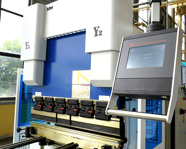
What Is Press Brake Software?
Press brake software is a tool used to calculate and simulate metal sheet bending, which provides a comprehensive solution for sheet metal bending.
Press brake software controls and guides the press brake by generating programmable codes, and providing accurate instructions for operators.
Press brake software has offline calculation tools for setup and bending sequence, as well as the ability to simulate bending.
Specifically, press brake software generates accurate bending data through advanced algorithms, including factors such as the best bending sequence, material characteristics, bending parameters, tool selection, etc.
Press brake software not only optimizes the bending process but also minimizes errors.
It can precisely control the bending angle and shape of the workpiece, thus ensuring better accuracy and consistency of the workpiece.
The 3D simulation function of press brake software can also visualize the finished product and simulate the bending process before actual production.
All these benefits translate into higher quality products, shorter delivery cycles, and better overall efficiency.
It can be said that press brake software comprehensively promotes manufacturing productivity.
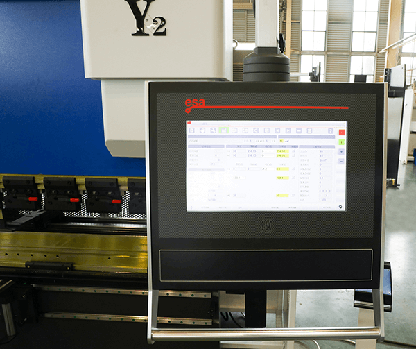
How Does Press Brake Software Work?
Actually, press brake software mainly operates based on finite element analysis (FEA) and numerical simulation technology.
Firstly, the CAD file is converted into a 3D model, then calculations are made based on FEA and numerical calculation methods.
Finally, the final bending parameters are obtained through simulation and optimization to achieve efficient and accurate metal material processing.
Here are the general steps for operating press brake software, although different types of press brake software have different functions and operational details.
Detailed operation steps still need to be referenced from the user manual of the press brake software.
Import CAD files: Import the CAD file of the parts (usually in DWG, DXF, etc. formats) into the press brake software.
Material and parameter setting: Input material characteristics, elastic modulus, etc., as well as relevant parameters of the press brake, such as clamping force, bending angle, and bending radius.
Layout and setting: Arrange the 3D model in the software and select the appropriate bending sequence according to requirements, which determines where to bend, use punches and dies, and bending order, etc.
Numerical calculation: After all parameters are set, the software performs numerical calculations on the entire model, typically using the FEA method.
This method discretizes the raw sheet metal into many small pieces, and then analyzes and calculates the mechanical properties of each small piece, obtaining its deformation and stress state.
Simulation and optimization: Use the simulation function provided by the software to simulate the bending process based on the calculation results, and perform model acceptance.
If there are problems with the model, it can be adjusted and optimized until it meets design requirements.
Output results: After completing the simulation, optimization, and other operations, the software outputs all the required parameter information for the bending process, which can be used for on-site operation in the factory.
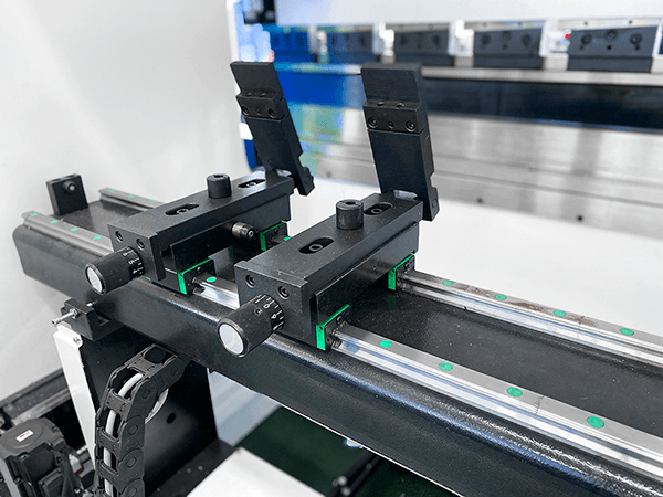
How to Improve the Accuracy of Press Brake Software?
Using a press brake for bending, even the slightest angle and size deviation can lead to rework or a scrap of workpieces.
The advanced features of press brake software greatly guarantee the accuracy and efficiency of workpiece bending.
Firstly, press brake software can predict modeling. Operators can model the bending process through tools such as CAD/CAM and 3D simulation software before actual processing.
By analyzing different simulation scenarios, problems can be discovered before the actual operation, and parameters, processes, tools, and materials can be optimized in time.
This can eliminate workpiece bending errors caused by design factors and reduce costs.
Secondly, press brake software has the function of automatic measurement and synchronized adjustment.
Sensing technologies such as laser scanners, cameras, or weighing sensors can be integrated with press brake software.
Real-time measured bending angles, positions, and bending forces can be fed back to the control system, which adjusts parameters according to predetermined targets.
This is more timely, and accurate, and ensures consistency and repeatability throughout the entire process than manual measurement in the past.
Finally, press brake software can analyze and optimize data. All data can be saved in the software. By collecting and analyzing previous bending operation data, press brake software can improve programs.
This optimizes the bending process and improves the accuracy, efficiency, and quality of workpiece bending.
When using press brake software, the following points should also be noted to maximize the optimization of the bending process.
Firstly, choose the bending angle and curve shape reasonably. Improper setting of the bending angle and curve shape can still cause problems with the workpiece.
Secondly, conduct sufficient testing. Before using press brake software for bending processing, it is necessary to conduct sufficient testing of relevant programs to ensure that they can operate normally and produce accurate workpieces.
Thirdly, continuously optimize and upgrade. The press brake bending software is a constantly evolving and maturing technology, and we need to constantly optimize and upgrade it to improve its performance and stability.
Advantages of Press Brake Software
In the past, bending operations mainly relied on experienced press brake operators to adjust manually.
This method may lead to bending errors. With the development of technology, the emergence of press brake software has changed the traditional sheet metal bending pattern.
Press brake software achieves automated, efficient, high precision, and high-safety production methods through digital control.
Compared with the previous press brake operation mode, press brake software has many advantages.
Higher Automation
Press brake software is an automated computer tool that can achieve automated operation through offline programming.
Press brake software provides standardized tools, programs, and shape libraries and simplifies the process of integrating different machine types.
By selecting the bending program, tool, bending parameters, and controller, the bending sequence can be automatically generated.
This reduces labor and time costs and can also improve bending accuracy and consistency.
Improving Accuracy and Efficiency
The automated process of press brake software reduces design errors and downtime and improves productivity and quality.
Programming allows operators to create efficient bending settings, reducing machine setup time and workpiece delivery cycles.
Press brake software has 3D part simulation and visualization functions, which can detect potential problems in advance, such as collisions and tool interference.
Press brake software uses mathematical models and algorithms to accurately calculate the bending angle and curve shape of the sheet metal.
This ensures the accuracy of bent workpieces, reduces the possibility of rework and scrap, and lowers production costs.
Improving the Safety of Operator
The automation of press brake software simplifies the bending process and reduces the operator's operating time, thereby improving safety.
The monitoring function of press brake software reduces the possibility of operators being injured by the machine through devices such as DSP.
Some complex steps can be automated through program settings, such as nesting parts and selecting tools, thus reducing the manual handling of heavy parts and tools.
The powerful functions of press brake software allow operators to produce high-precision workpieces without needing to master too complex bending techniques.
High Production Flexibility
Press brake software can generate different programs according to different production requirements, so it can quickly adapt to different production needs.
Production management can also be achieved through remote control, improving production flexibility, efficiency, and safety.
Multi-Language Support
With the increasing internationalization of the manufacturing industry, multi-language support has become an important requirement.
Now, press brake software can support multiple languages, and users from different countries and regions can operate more conveniently.
Common Press Brake Software
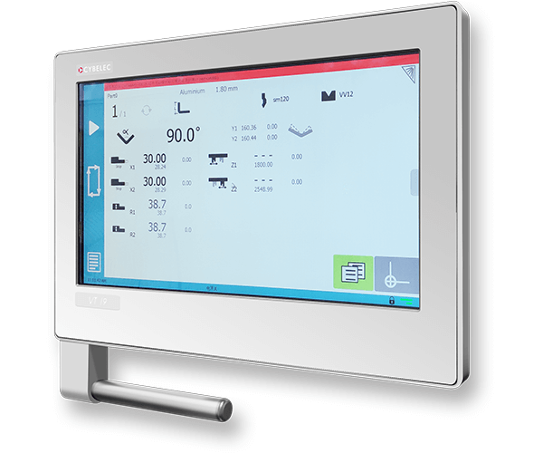
Press brake software has different brands, and the same brand also has different models. The following introduces some common press brake software.
AMADA
Amada is a globally renowned machinery brand. Its press brake software provides powerful functions for its own press brakes.
Its software can achieve remote control and management through automation and can predict and optimize bending processing products.
It can also predict based on different materials and requirements to provide the best processing plan and reduce human errors.
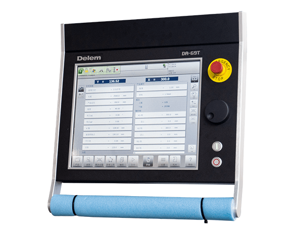
Delem
Delem software from the Netherlands is designed specifically for CNC press brakes.
It supports multiple languages and operating systems and can achieve efficient and accurate bending processing.
Delem is characterized by its simple operation, accurate calculation, and good stability.
LVD
The most distinctive feature of LVD press brake software is its intuitive interface, which allows operators to easily program and optimize bending operations.
LVD software also provides advanced features such as automatic gear positioning and customizable tool libraries.
LVD press brake software can be compatible with different press brakes, reducing the cost of software replacement.
Bystronic
Bystronic, a German brand, provides comprehensive offline programming solutions for CNC press brakes.
The 3D simulation function of Bystronic's press brake software can visualize the entire bending process in 3D.
It can be integrated with CAD/CAM software, production management software, and intelligent data analysis tools.
Trumpf
Trumpf's software also has advanced features such as automatic bending sequences, automatic tool selection, and tool setting optimization.
Operators can interactively change programming parameters, customize bending simulations, and maximize speed, quality, and efficiency.
Factors to Consider When Choosing Press Brake Software
Compatibility
Before choosing press brake software, the compatibility of the software with the current hardware should be considered first.
Compatible press brake software and existing systems can ensure smooth workflow.
Level of Automation
The level of automation of press brake software ranges from basic software to fully automatic software.
Choose the appropriate level of automation software according to your production needs. A simple bending process only requires manual or semi-automatic software.
At least it should have the ability to accurately calculate the best bending sequence, tool settings, and bending parameters.
For a complex bending process, it is best to choose fully automatic press brake software.
Technical Support
After purchasing press brake software, technical support and training services from the supplier are required.
The team can better use the tools after training and can consult the supplier for difficult-to-solve problems.
Ease of Use
Choose press brake software with a user-friendly interface that is easy to use. This can reduce the user's learning difficulty and create bending programs faster.
Budget
According to your production needs, research the various functions of press brake software and choose press brake software that is suitable for your business based on the budget.
Different brands have a large price differences, and you need to understand the functions and characteristics of different brands in detail before choosing the appropriate one.
Conclusion
Press brake software has revolutionized the production methods in the sheet metal processing industry.
Using press brake software has many advantages, greatly improving production efficiency and product quality.
Press brake software provides various automation functions through programmings, such as automatic bending sequence calculation, tool selection and setting, and gear stop positioning setting.
Press brake software also provides an offline programming function, which can be used for remote bending and management.
It can also be integrated with CAD software to perform 3D simulation bending and detect potential problems in advance.
Before choosing press brake software, it is necessary to evaluate your business needs, budget, and the quality and service of different brands.
FAQs
Is press brake software compatible with different press brakes?
In general, the control software and other software used by press brakes of the same brand and model are not compatible.
These brands and models of press brakes have their unique operating systems and data communication protocols.
Therefore, press brake software needs to be customized and adapted according to specific brands and models to ensure compatibility with the corresponding press brakes.
If you want to be compatible with control software between different brands and models of press brakes, additional programming and configuration work may be required.
Can press brake software be integrated with other software programs?
Press brake software can usually be integrated with other software programs, such as CAD software.
Integration between different software is achieved through using APIs (Application Programming Interfaces) or file export/import functions.
Some brands of press brake software may provide APIs that allow other software to communicate and interact directly with the software.
Custom scripts or plug-ins can be written to automate some tasks or transfer data from one software to another.
There are also some press brake software that provides file export/import functions, which makes it possible to share data between them and other software.
For example, parts can be designed in CAD software, exported as DXF or DWG files, and then imported into press brake software for further processing.

 English
  Arabic
  German
  Spanish
  French
  Portuguese
  Japanese
  Russian
  Chinese