I've cleaned up enough shattered tool steel to recognize the sound when a die bursts under pressure—it echoes like a shotgun blast inside a container. Typically, the operator at the pedal is staring at his hands, trying to figure out what went wrong. He did the calculation: took his quarter-inch mild steel, multiplied the thickness by eight, and installed a two-inch V-die in the bed. He followed the internet’s so-called golden rule.
But a press brake doesn't care about online formulas—it obeys physics.
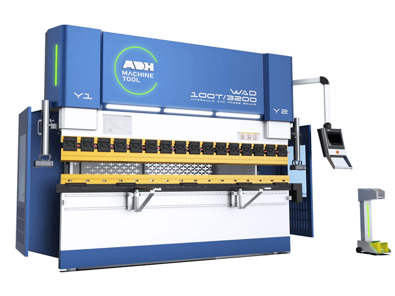
Treating a thirty-ton ram as a simple equation is how you end up with a damaged machine and a visit to the emergency room. For shops that want precision and built-in safeguards rather than guesswork, explore ADH Machine Tool’s CNC press brake; its advanced control system and finely tuned automation help prevent the miscalculations that lead to costly damage.
The "Rule of 8" Is a Hazardous Shortcut, Not a Selection Method
Why thickness-based multipliers seem safe yet conceal crucial machine factors
Check any bending chart posted on a shop wall. At its center sits the familiar formula: V-die width equals eight times the material thickness. It’s printed there because, under ideal conditions with standard mild steel, it produces a clean 90-degree bend with consistent springback.
Formulas like that feel reassuring. They give a tidy, predictable outcome in a noisy, hectic workshop.
Picture a press brake as a high-powered rifle—you don’t load just any bullet because it appears to fit. The caliber must match the chamber, and the barrel must be capable of handling the pressure. The Rule of 8 presumes the machine’s clamping system—the chamber—is ready for any die width the multiplier dictates. It assumes a 13-millimeter European tang or a 20-millimeter auto-clamping setup will seat correctly and withstand the load. When you choose tooling based solely on material thickness, you overlook whether the machine can actually secure the die safely.
The hidden cost of assuming standard V-dies suit every metal
Take a piece of high-tensile steel and try bending it with the same standard V-die you used for mild aluminum. The calculations might suggest the same die if the thickness is equal, but the material will quickly prove otherwise.
High-tensile steel resists deformation and needs far more force to yield, so the pressure required for bending rises sharply. If you drop a standard V-die into the bed simply because a multiplier told you to, you ignore the material’s hardness and the specific punch geometry needed to shape it. For a basic L-shaped air bend, nearly any punch shape might work, which can make the V-die rule seem even more convincing to inexperienced users.
Once you move beyond standard mild steel, that broad assumption falls apart. You end up forcing a tool to handle a task it wasn’t built for, wearing away the precision edges that ensure part accuracy.
What really happens to the ram when you disregard machine tonnage limits to achieve a "perfect" bend?
A typical 10‑foot press brake might be rated for 100 tons of force. If you bottom out a die while trying to achieve a tight radius on thick plate because the Rule of 8 indicated the die opening was adequate, that force doesn’t simply disappear.
It moves directly up through the punch, into the tool holder, and then to the ram.
The ram is the large upper beam of the press that drives the punch downward. It appears indestructible, but it is not. Exceeding the machine’s tonnage limit causes the center of the ram to bow upward under stress—a phenomenon known as ram deflection. Over time, or sometimes in a single catastrophic hit, this deflection can become permanent. That means you’ve bent the backbone of a hundred‑thousand‑dollar machine while producing a twenty‑dollar part. To prevent this, you must begin not with the metal, but with the machine that holds the tooling.
The Non‑Negotiable First Filter: Your Brake’s Clamping DNA and Daylight
I’ve seen operators unpack a brand‑new precision‑ground punch, admire its flawless finish, and only then notice the tang doesn’t fit the ram. They’ve effectively bought an expensive paperweight. Before calculating a single bend allowance or considering material thickness, you must confirm that the tool can physically fit inside your machine.

European, American, and WT styles: Are these simply different mounts, or entirely distinct tooling systems?
Approach a press brake and examine the upper beam. The slot cut into that steel defines the machine’s identity. If it’s designed for an American‑style tang—a centralized half‑inch‑wide protrusion—it expects tools that rest on the tang or shoulder, depending on the holder. A European style (often called Promecam) uses an offset tang with a safety groove, ground to ±0.0005‑inch precision, transferring the load through the tool shoulder into the beam. Wila/Trumpf (WT) or New Standard systems employ a button‑release mechanism that locks tools in automatically.
For a deeper technical breakdown of how each clamping style affects compatibility and accuracy, see ADH Machine Tool’s guide on press brake tools, which draws on their R&D expertise in CNC-based bending systems to illustrate these mounting differences in practice.
These aren’t merely differently shaped slots—they represent completely separate tooling systems.
If you purchase American tooling for a European clamp, it simply won’t fit. The real problem, however, lies in the use of adapters. Some shops install adapter rails to mount inexpensive American punches on high‑end European brakes. This suddenly creates major height inconsistencies across the bed, forcing hours of shimming just to bend a basic bracket and wasting valuable setup time. Committing to a tooling style means committing to a particular method of transferring tons of force. But what happens when the physical size of those tools exceeds the capacity of the machine itself?
The open‑height constraint: How your machine’s daylight defines your maximum punch length
Measure the distance from the top surface of the lower bed to the bottom of the upper ram when the machine is completely open. That distance is known as your “daylight” or open height, representing the absolute physical limit of your machine.
Imagine you need to bend a six-inch-deep box. You browse a catalog and find an eight-inch-tall gooseneck punch that perfectly clears the return flanges, so you order it. When it arrives, you mount it into the ram, place a standard four-inch V-die on the bed, and step back. The punch tip already sits inside the V-die before you even press the pedal—you neglected to subtract the tooling height from the daylight.
If your press brake offers a 14-inch open height, using an eight-inch punch and a four-inch die leaves you just two inches of clearance. That space isn’t even enough to insert the flat sheet, let alone remove a six-inch-deep formed box.
Daylight determines the maximum punch length and thereby the deepest part your machine can form. To calculate the correct punch height, start with the machine’s open height, subtract the stroke needed to clear the part, then subtract the die height. Only after doing this can you know how tall the punch can be. Once you confirm the tool fits within that limit, how can you ensure it stays secure during a hurried mid-shift changeover? For larger setups that demand extended daylight and synchronized tonnage control, the CNC precision and automation of ADH Machine Tool’s Tandem Press Brake provide the efficiency and consistency needed to handle complex bending sequences without compromising speed or safety.
Tangs, safety clicks, and seating: How your tool change process defines what you can safely buy
If you loosen the clamp on a traditional American-style punch without supporting it, gravity will do the rest—a forty-pound block of hardened steel can fall straight onto the die or, worse, onto your foot.
This is what led to modern tooling designs. European styles incorporate a safety groove in the tang. When the clamping plate is released, a pin or lip engages that groove, holding the tool suspended so it can be slid sideways out of the machine. Wila/Trumpf configurations advance the idea with spring-loaded safety clicks—press a button, the tool drops in, locks into position, and stays upright on its own.
Your method of tool change determines what equipment you can safely use. If your shop performs five setups per shift, using conventional drop-out tooling without safety grooves virtually guarantees injury. Yet these safety features do more than protect workers—they ensure the punch seats perfectly against the ram shoulder. A misaligned punch, even by a fraction of a millimeter from a poorly seated tang in an auto-clamp, redirects the ram’s force sideways instead of straight down. That side load can shear the tool edge, damage the part, and transmit destructive shock through the machine frame.
Proper fit and secure seating are only the starting point. What occurs when thousands of pounds of unseen force finally act on that precisely seated tool?
The Tonnage Reality Check You’re Probably Misjudging
Air bending a 10‑gauge sheet of mild steel over 90 inches using a standard 1‑inch V-die requires 9.6 tons of force per foot. Multiply that length, and your press brake exerts roughly 72 tons to form the part. Most machines and tooling combinations handle this easily. But notice what happens when an inexperienced operator decides the inside radius is too large and switches from air bending to bottom bending. The force multiplier changes dramatically—what required 72 tons can double or even triple, exceeding 200 tons. The hydraulic rams apply exactly what they’re told to apply, but the tooling, rated far lower, shatters violently, sending fragments of hardened steel across the shop floor.
The machine performed exactly as instructed. The failure occurred because the operator assumed that if the sheet metal fit into the die, the die could withstand the bend. They treated the press brake’s total capacity as assurance that the tooling would survive. To preserve your tools and keep operators safe, you must shift focus from the machine’s maximum tonnage to the specific load rating stamped on your punch. Yet, when you examine that stamp, how do you interpret the numbers to determine a safe working limit for the part in front of you?

Tons per foot vs. tons per inch: Which number actually prevents your tooling from cracking?
If you look through three different tooling catalogs, you’ll encounter a jumble of measurement units. One manufacturer rates a punch at 29.2 kN/m, another lists the same profile at 26.5 metric tons per meter, and a third marks it as 10 U.S. short tons per foot. This confusion of units is the hidden cause of many tool failures. Operators see a rating of “10 tons,” assume the tool can handle a 10-ton bend, and press the pedal.
That assumption misinterprets how force is distributed. A rating of 10 tons per foot denotes force density, not total capacity. It indicates that the tool can safely absorb 0.83 tons for every inch of its length (10 tons divided by 12 inches). If you bend a 24-inch panel that requires 12 tons of total force, you’re applying 0.5 tons per inch, keeping the tool well within its safe range.
Now consider a thick, 3-inch-wide stainless steel bracket requiring 6 tons of total force to bend. Six tons seems below the “10-ton” marking on the tool, correct? But calculate it: six tons concentrated over just 3 inches equals 2 tons per inch. That’s more than double the maximum rated load per inch for the punch. The tool will shear or crack because the per-foot density rating was mistaken for total capacity. Once you realize how easily a small, tough piece can exceed localized limits, you might wonder: won’t the machine’s safety systems intervene before the tooling fails?
Tooling load limits vs. machine capacity: Which one gives way under pressure first?
A 150-ton press brake is unaware that it’s fitted with a 20-ton die. Its hydraulic system pushes until reaching the set depth or its own 150-ton overload limit. If you program a bend requiring 50 tons of force, the relief valves remain closed, and the brake readily delivers all 50 tons directly into the tooling.
Exceeding the tooling’s rated tonnage seldom damages the machine first; the tooling fails independently. Hardened tool steel doesn’t yield when overloaded—it fractures. The danger lies in operators trusting the machine’s tonnage gauge as a safeguard. They see the readout at only 30% of maximum capacity and assume it’s safe, while the punch tip undergoes severe microscopic cracking.
Your machine’s capacity is the measure of its hammer, while your tooling’s load limit is the strength of its anvil. Striking a brittle anvil with a heavy hammer leaves the hammer unharmed but shatters the anvil. You must compute the required force based on material, thickness, and die width, then confirm that value is below the tool’s rated limit. But even when the calculations check out and the rating is sufficient, what happens to the tooling’s structure when massive localized loads are repeatedly applied to the center of the bed?
Risks of concentrated loading: Why bending short parts on long, high-tonnage dies leads to permanent tooling deflection
Insert a 4-inch piece of half-inch-thick plate into the center of a 10-foot, high-tonnage V-die. The die might be rated for 50 tons per foot, while your short, thick part needs only about 15 tons of force. On paper, you remain within the safe tons-per-inch limit. You make the bend, and the part turns out fine.
However, this creates a severe concentrated load. When the ram descends, the outer ends of the 10-foot die bear no pressure, while all 15 tons are focused at the center. Repeatedly bending short, heavy parts in the middle of long tooling gradually causes permanent deflection. The tool steel compresses and wears faster in the center than at the edges. The press brake’s bed and ram also deflect slightly from the localized stress, a phenomenon called machine deflection.
Eventually, you place a 10-foot sheet of thin-gauge aluminum into that same die. After bending, the part comes out distorted—the ends are over-bent while the center is under-bent. The machine settings haven’t changed, but your long die has developed a microscopic “swayback” at its center from the repeated localized impact of short, heavy brackets. To prevent this, short parts should be bent using short, segmented tooling. Load only the die length you actually need so the machine’s crowning system can properly distribute the force.
Once you avoid crushing your dies by respecting localized force limits and matching tool length to part length, the mechanical stresses are controlled. The next challenge is geometric: how to position the punch within the die without hitting the flanges you’ve already formed.
Selecting the Punch: Why Part Geometry Determines the Profile Before the Angle

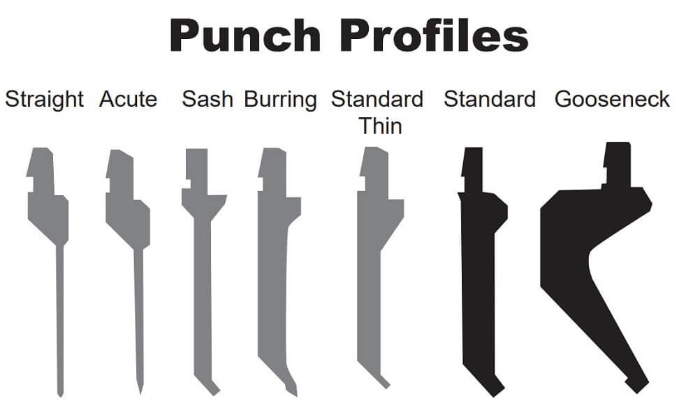
Straight, gooseneck, or sash: Which shape truly clears your return flanges?
Picture forming a deep U-channel box. The first 90-degree bend using a standard straight punch goes perfectly. But when you flip the part for the second bend, that initial 4-inch return flange rises at about 20 degrees per second and crashes directly into the solid body of the punch. The machine strains, the part collapses, and you end up with scrap metal.
Simple L-shapes are easy because the material bends into free space, so nearly any punch shape can be used. Once a return flange is introduced, however, the part’s geometry fully dictates the tool selection. A gooseneck punch isn’t chosen for producing a better bend angle—it’s chosen because its recessed center provides clearance for the moving material. A sash punch performs the same function for complex Z-bends, with its tip offset from the tool body to allow tight step bends to pass under the ram.
At this stage, you do not select the punch based on material thickness.
You select it based on the space the part must occupy during the bending stroke. Attempting to save setup time by using a straight punch in place of a gooseneck will likely trap the material between die and ram. Since the punch shape depends entirely on the clearance your part requires, the next question is how to determine whether that space is sufficient.
Collision inspection: Identifying clearance problems on paper before lowering the ram
In nearly every fabrication shop, you can find a gooseneck punch marked by a shiny gouge just above its relief cut. That scar signifies a reactive collision check: an operator assumed the flange would clear, pressed the pedal, and let the machine discover the mistake.
You cannot determine a bending sequence by sight alone.
As the punch lowers, the sheet does more than fold—it travels along an arc. To confirm clearance, you must map the final bent shape against the punch’s 2D cross-section at the point of maximum depth. If a return flange intersects the punch body in this layout or within your control software, it will crush the part in the press. The overbend required to offset springback must also be included. For instance, forming stainless steel to 90 degrees may require pressing it to 87 degrees. That three-degree difference moves the return flange much closer to the punch body, often changing a safe operation into a collision. After confirming the punch body clears the flanges, the question remains: what occurs at the punch tip when it meets the metal?
The sharp tooling problem: When does a small tip radius start piercing the workpiece?
European-style precision tooling is ground to a ±0.0005-inch tolerance. That may appear excessive for forming unclean sheet stock until a sharp-tipped punch is installed in a loose clamp with only 0.002 inches of play.
When the ram applies force, that minute looseness lets the punch shift slightly off-center. If the punch has a tip radius smaller than 63% of the material thickness, this deviation turns a bending tool into a cutting one. The narrow tip focuses the press’s entire load into a microscopic line. Instead of wrapping the sheet evenly around the radius, the punch bites into it, scoring the surface and forming a severe stress riser along the bend that will later crack under stress.
Online advice often says to size the punch radius to half the material thickness. That rule presumes a perfectly rigid setup with the punch aligned exactly each time. In practice, tool wear, clamp looseness, and localized deflection make it necessary to use a slightly larger tip radius to distribute load evenly and prevent cutting. Once the punch clears the flanges and the radius safely spreads the tonnage, the next question is how to determine the correct opening for the die below.
Sizing the V-Die: Applying the Rule of 8 with the corrections it truly requires
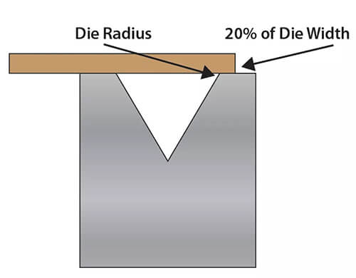
Take a precision-ground V-die marked 0.250-inch and measure it with digital calipers—you’ll get 0.236 inches. Premium press brake dies are built to metric specifications, making that “quarter-inch” die actually 6 millimeters. This 0.014-inch difference shows that the well-known Rule of 8 is already mathematically off before operation begins.
According to the rule, the die opening should equal eight times the material thickness. For 14-gauge mild steel (0.075 inches), that equates to 0.600 inches. In practice, you’ll probably use a 0.625-inch (16 mm) die because it’s standard stock. The rule is not a fixed law of physics but a convenient approximation that yields a stable internal bend radius in mild steel, allowing an elliptical curve to form without excessive tonnage. Treating it as an exact formula ignores the underlying mechanics. If the rule is only an estimate, what happens when the material itself behaves differently?
How yield strength alters the safe multiplier from 6x to 12x
Try bending half‑inch AR400 abrasion‑resistant steel in an 8x die (4 inches), and you will hear a sharp crack. The metal splits right along the bend. Mild steel bends smoothly with an 8x opening, but higher‑strength materials resist forming with extreme force. Forcing a rigid, high‑tensile sheet into a narrow V‑die compresses the inner bend radius too much, surpassing its ductility and tearing the outer fibers.
To prevent cracking, the die must be widened. Stainless steel generally calls for a 10x multiplier to ease the inside radius and lower the required tonnage. For thick, high-strength plates, that factor increases to 12x. In contrast, very ductile metals such as soft aluminum can sometimes use a 6x multiplier to produce a tighter radius without causing tears. The multiplier simply represents a variable scale governed by the metal’s yield strength. After determining the correct die width to prevent fracture, the next question is how to define the shape of the V-groove itself.
Air bending vs. bottoming: Does the selected bending method affect the required die angle?
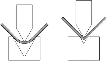
Place a 90-degree punch into a 90-degree die with a sheet of metal between them and press until the machine reaches full force. This operation is called bottom bending. In this process, the punch physically forces the material into the V-groove so that the metal assumes the die’s exact angle. If a 90-degree bend is needed, a 90-degree die is required. The geometry of the tooling is fixed.
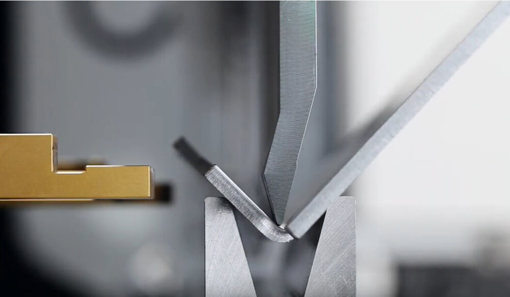
Air bending functions under a completely different principle. The material touches the die only at its two shoulders, while the punch descends into the empty space between them. The resulting angle depends entirely on how deep the punch travels, not on the die’s included angle. Using the same 85-degree V-die, you can produce 120-, 100-, or 90-degree bends simply by adjusting the ram depth. Bottoming demands matching the die angle to the print, whereas air bending only requires the die angle to be acute enough for the punch to achieve the desired depth. If air bending offers such versatility, why not use a 90-degree die to air-bend a 90-degree part?

The acute angle solution: Why an 85-degree die may be necessary to obtain a precise 90-degree bend in springy metals
Bend a piece of 304 stainless steel to exactly 90 degrees under load, and as soon as the ram retracts, the flanges will rebound to about 93 degrees. Every metal possesses an elastic zone. During bending, the outer fibers stretch and the inner fibers compress. Once the applied force is removed, these fibers partially return toward their original flat condition.
To end with a true 90-degree bend, the punch must travel deep enough to force the material to 87 degrees initially. With a 90-degree die, however, the punch will bottom out against the die faces before reaching that needed overbend. The press will stall, tonnage will surge, and the part will still return out of tolerance. This is why air bending depends on acute dies—commonly 85 or 86 degrees. The sharper die angle provides the required clearance for the punch to overbend the sheet, allowing it to relax precisely to a square 90-degree result. Once punch and die are sized for clearance, tonnage, and springback, the next step is ensuring that the selected tooling can endure the actual bending process.
Complete Tooling Selection Sequence: From Machine Specifications to the First Bend
To make sure your selected tooling withstands the extreme forces of the bending process, stop viewing the press brake as a simple vise. Think of it as a high-powered rifle: you would never load a random cartridge simply because it fits. You match the caliber to the chamber, verify that the barrel can tolerate the internal pressure, and check all clearances before firing. Treating tooling choice as a casual step—grabbing any die that seems to match the material thickness—can lead to severe equipment damage. A disciplined, reverse-engineered procedure is required to eliminate mistakes before the metal even meets the die. So where does that process start?
For manufacturers who need that same disciplined precision scaled to heavy industrial work, consider the Large Press Brake from ADH Machine Tool. Its CNC-controlled frame and verified rigidity maintain bending accuracy under high tonnage, turning theoretical setup discipline into real-world consistency on thick or oversized parts.
Step 1: Verify clamping style, daylight, and available tonnage before consulting any catalog
The process starts with the machine’s inherent physical constraints. Before reviewing a blueprint, determine your clamping configuration. If the ram is built for European-style tangs, you are confined to that system. Precision-ground European tooling maintains tolerances around ±0.0005 inches, so every punch used in a staged setup must have the same height profile. Mixing tools with different heights transforms a nominally “compatible” clamping system into a persistent setup problem that demands frequent and risky machine readjustments. Once the clamping type is confirmed, measure the open daylight to ensure the punch, die, and part fit together within the machine’s window. Then calculate your available tonnage per foot. If the press provides up to 12 tons per inch, any tooling rated for less could fracture under load. With the machine’s limits defined, the next question becomes how to choose the punch shape.
For guidance on validating your specific press brake configuration or to compare tooling options that align with these machine parameters, consider reaching out to ADH Machine Tool. Their CNC-based bending systems and disciplined engineering process ensure precise compatibility assessments and reliable performance from the start.
Step 2: Relate part geometry to punch type, then perform the collision check
Next, map the part’s collision profile, starting with the simplest suitable tool. Beginners often overcomplicate their selection, purchasing costly, deep-relief gooseneck punches for straightforward L-bends. Almost any standard straight punch can form a basic 90‑degree bracket without interference. This approach conserves both budget and setup time. Move to specialized shapes—such as acute goosenecks or sash punches—only when the part includes deep return flanges that would otherwise strike the ram during bending. Compare the part’s final folded form with the punch profile to ensure the material swings freely. Once the top tool is confirmed and collision-free, the next challenge is finalizing the die without repeating the Rule of 8 mistake.
Step 3: Determine V-die width based on material data rather than catalog defaults
V-die sizing requires comparing the material’s yield strength to the part’s shortest flange, treating catalog standards with caution. The Rule of 8 presumes ample material over the die shoulders, yet real parts often have short flanges that could slip into the V‑groove if the die is too wide. To support that short flange, a narrower V‑die is required. Reducing the die width greatly increases the tonnage needed for the bend. A die rated for standard mild steel work can easily crack if forced to form a short-flange, high-yield plate. You must calculate the actual tonnage the narrower die will experience, confirm it remains within the die’s rated limit, and ensure the press can supply that force without surpassing its tons‑per‑inch constraint. Once the calculations validate both upper and lower tools, one last physical verification remains.
For engineers who need verified tonnage tables and die compatibility data, ADH Machine Tool provides detailed technical references covering CNC press brake, bending, and automation solutions backed by continuous R&D investment. You can review these specifications in the downloadable ADH Machine Tool brochure.
Step 4: Confirm the complete setup at a single station before starting production
Finally, install the tools at one station and ensure the physical conditions match your calculated setup. Industry guidance often suggests buying a wide array of high‑end tools and letting operators work it out on the floor, but that practice damages rams. Seat punches fully, align dies precisely, and lower the ram slowly under minimal pressure to verify clearance. Test with one scrap piece from the actual production batch. Pay attention to machine sounds, tonnage readings, and springback measurements. If tonnage spikes or a collision occurs, it will happen during this controlled trial rather than on a high-speed run. Tool selection is not simply matching tool size to material thickness—it is an engineering process that retraces the machine’s clamping design, tonnage capacity, and geometric constraints to protect the equipment from operator error. By honoring the inherent physics of the press brake, the metal will perform exactly as intended.