
How a shear cuts: deformation followed by controlled fracture
A shear does not slice through the full thickness of metal like a knife. Its opposing blade edges concentrate force into a narrow region, permanently deforming the metal until cracks develop and complete the separation. This controlled fracture explains why cutting performance depends on more than blade sharpness: the sheet must be positioned and restrained, and the blade setup must suit the material. For a broader introduction to the equipment behind this process, ADH Machine Tool, whose CNC equipment portfolio includes shearing machines, explains the fundamentals in What Is a Shearing Machine?.
What the upper blade, lower blade, backgauge, and hold-downs do
In a typical shear, four components divide the work of cutting, positioning, and restraint:
- Upper blade: Moves downward and applies the cutting force.
- Lower blade: Provides the opposing cutting edge. Together, the blades concentrate stress along the intended cut line.
- Backgauge: Provides a positioning stop that establishes the cut length relative to the blades. It locates the sheet; it does not clamp it.
- Hold-downs: Clamp the sheet during cutting, limiting lifting, shifting, and vibration as the blades load the metal.
Positioning and restraint solve different problems. A correctly set backgauge establishes the intended dimension, but movement during the cut can still spoil it. Hold-downs help preserve that position under load. They are workholding devices, not substitutes for machine guarding or keeping hands outside the cutting area.
Why the metal deforms and cracks rather than simply being sliced
Under the initial load, the metal deflects elastically—meaning it could recover its shape if the load were removed. As local stress exceeds its yield strength, the point at which permanent deformation begins, the metal bends and flows near the blade edges. This permanent change is called plastic deformation.
The blades pass one another with a small gap called blade clearance. Metal near that gap experiences concentrated compression, bending, and shear, which tends to make adjacent regions slide past each other. Eventually, the material cannot accommodate further local deformation without cracking. With suitable clearance, cracks originating near the opposing cutting edges meet through the thickness and separate the sheet. The blades therefore do not need to penetrate the entire thickness before separation occurs.
The cut edge records this mechanism. A smoother burnished zone, formed by blade contact and deformation, can sit beside a rougher fracture zone, where cracking completed the cut. A fracture zone is therefore not automatically a defect. Its appearance must be judged alongside burrs, distortion, and dimensional accuracy; one edge feature alone does not establish the cause of a poor cut.
This changes how to think about setup. Material strength and thickness determine the demand placed on the machine. Clearance influences deformation and how the cracks meet. Rake, the upper blade’s inclination along the cut, spreads cutting engagement along the sheet rather than loading the whole width at once, reducing peak force. Restraint limits unwanted movement. These are controls over the separation process, not incidental adjustments to a simple slicing action. For equipment selection, ADH Machine Tool’s CNC-based shearing machine portfolio offers a starting point for evaluating capacity and setup requirements against the materials and cuts your work demands.
Set up the machine for the material and cut

Set up in prerequisite order: confirm that the job is within capacity, inspect the machine under approved safety procedures, then establish blade settings, sheet position, and restraint. A trial cut checks the completed setup; it is not a way to discover whether an uncertain job exceeds the machine’s limits.
Check material strength, thickness, and cut length against the machine’s rated capacity
Identify the material grade and strength, measure its thickness, and establish the length of the cut along the blades. Compare that combination with the manufacturer’s capacity guidance. Here, cut length means the span being sheared, not the finished dimension set by the backgauge. If you are comparing equipment for these requirements, download the ADH Machine Tool brochures to explore its CNC shearing offerings, then confirm the intended material, thickness, and cutting span against the specific machine’s capacity documentation.
A thickness rating for mild steel does not automatically apply to stainless or higher-strength sheet. Stronger or thicker material increases cutting demand, while the span being cut affects blade engagement. Check the applicable capacity table and its conditions rather than relying on a single maximum-thickness label.
If material properties are unknown or the job falls outside the documented limits, stop and obtain confirmation or choose a suitable machine. To discuss material specifications and suitable machine capacity, contact ADH Machine Tool, whose network of more than 50 sales and service points in China and overseas supports equipment inquiries. Any proposed cut must remain within the machine’s documented limits. Neither clearance nor rake makes an over-capacity cut acceptable.
Inspect blades, guards, and sheet supports; follow approved adjustment and energy-isolation procedures
Check both blades for contamination, nicks, chips, rounded edges, loose fasteners, and misalignment using the approved inspection procedure. Wear or damage can increase cutting force and produce burrs or uneven edges; changing a setting cannot repair a damaged blade. Check guards, protective devices, and sheet supports as well. Supports must carry the sheet without allowing sag that disrupts positioning.
Distinguish routine operator controls from work requiring authorized personnel. A trained operator may select permitted settings through normal controls, but blade handling, mechanical adjustment, or entry into a hazardous area requires the specified energy-isolation procedure. That includes controlling stored energy and securing components against movement—not merely pressing the stop button. Do not bypass guards to inspect or adjust the machine, and resolve defects before cutting.
Set blade clearance—the gap between the cutting edges—using material-specific manufacturer guidance
Blade clearance is the gap between the passing cutting edges. Select it from the machine or tooling manufacturer’s guidance for the actual material and thickness, then set and verify it by the approved method. Do not transfer a setting from another alloy or use a universal percentage of thickness.
Clearance affects how the metal deforms and how cracks from the opposing edges meet. Too little clearance can increase force and blade wear; too much can increase burrs, rounding at the edge, and rough fracture surfaces. These tendencies explain why the gap must suit the material, but they do not make a burr conclusive evidence of incorrect clearance: blade wear can produce similar symptoms.
Record the starting setting so that the later trial cut can be compared with a known setup.
Understand rake angle: progressive cutting reduces peak force but can increase strip distortion
Rake angle is the blade’s inclination along the cut. It makes engagement progress from one end toward the other rather than loading the full cut length at once. Clearance controls the gap between the edges; rake controls how engagement spreads along them.
Greater rake generally reduces peak cutting force because less material is being cut simultaneously. The trade-off is possible strip twist or distortion, especially with thin material. Lower peak force therefore does not necessarily mean a better finished part.
Where rake is adjustable, use the manufacturer’s material-specific guidance and permitted adjustment procedure. Where it is fixed, treat it as a machine characteristic, not an operator setting. Any permitted change must still leave the job within the documented capacity limits.
Set the backgauge and squaring guide; check hold-down settings to prevent slipping without marking the sheet
Set the backgauge for the required finished dimension, accounting for the machine’s stated gauging convention. Confirm that the sheet seats properly against it and that the squaring guide locates the sheet square to the blade. A correct gauge display cannot compensate for a sheet that is skewed, sagging, or not touching the stop.
Check hold-down settings using the approved procedure. Restraint must prevent slipping, lifting, and sideways movement without marking or crushing the surface. Too little or uneven restraint lets the sheet move under cutting load; excessive clamping can damage an otherwise acceptable part. Begin the stroke only when the sheet is supported, positioned, squared, and fully restrained, with safeguards in place.
After completing setup, make a representative trial cut under normal guarded operation. Measure the finished dimension and squareness, and inspect burrs, edge straightness, strip twist, and clamp marks before production. Treat defects as clues requiring confirmation, not automatic instructions to change clearance. During the stroke, the established gap governs separation, rake spreads blade engagement, and the hold-downs preserve the position established by the gauge and guide.
Follow the cutting cycle from positioning to separation
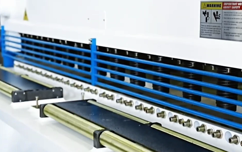
At each point along the cut, the blade first deforms the restrained metal, then drives fracture through the remaining thickness. With rake, different points enter this sequence at different times as blade engagement advances along the sheet.
Position and support the sheet while keeping hands clear of blades and hold-downs
Use the machine’s approved handling method to seat the sheet against the backgauge or stops and the squaring guide. Supports must keep it flat: sag can change how the sheet seats and leave it incorrectly positioned before cutting begins.
Keep hands outside both the blade’s shear zone and the hold-downs’ pinch zones throughout positioning and cycling. If the sheet cannot be positioned without entering those areas, stop and arrange an approved handling method rather than reach past safeguards.
Hold-downs secure the sheet before the blade contacts it
The hold-downs press the sheet against the machine bed before blade contact. This restraint matters because cutting forces can lift, drag, or vibrate an unsecured sheet. Movement would shift the intended cut line relative to the blade, even if the sheet originally touched the gauge correctly.
Clamping preserves the established position during loading. It does not replace guarding or make nearby hand placement safe.
Initial contact causes local elastic deformation, then permanent deformation
The sheet does not separate at first contact. The initial load causes elastic deformation—a recoverable change in shape. If the load disappeared before yielding, that deformation would recover.
As the blade advances, stress near the cutting edges rises beyond the material’s yield strength, the stress level at which permanent deformation begins. The metal then bends and flows locally, producing plastic deformation: a change that remains after the load is removed. The sheet is changing shape, but a continuous bridge of metal still connects its two sides.
Blade penetration forms a smooth burnished zone as cracks begin to develop
Further blade travel forces metal past the opposing cutting edge. High contact pressure, plastic flow, and sliding contact with the blade create the burnished zone, a smooth, often shiny band on the cut face. This band records the part of separation produced by blade penetration and shearing before final fracture.
Continued deformation concentrates stress and strain near the upper and lower cutting edges. Cracks begin in these highly loaded regions and grow into the sheet; they do not simply appear halfway through its thickness.
Cracks propagate from the blade edges and meet to separate the metal
The cracks advance through the remaining ligament—the bridge of unbroken metal between them. With the sheet restrained, blades aligned, and clearance appropriate for the material and thickness, the opposing cracks meet and complete separation. The blade therefore does not need to pass through the entire thickness before the metal breaks apart.
Fracture leaves a textured region beside the smoother burnished band. That texture is an expected result of crack growth, not automatically a defect. Material behavior and cutting conditions affect how much penetration occurs before separation, so the relative sizes of the two regions are not a universal quality standard.
The blade returns and hold-downs release; retrieve the part only through the approved safe-handling procedure
After separation, the blade returns and the hold-downs release according to the machine’s cycle. A returned blade alone does not establish that access is safe. Retrieve the part and offcut only through the approved safe-handling procedure, keeping clear of remaining pinch hazards and accounting for sharp edges. A trapped piece requires the specified intervention procedure, not an improvised reach into the machine.
The next step is to inspect the safely retrieved trial cut. Its edge regions reveal how separation occurred, but appearance alone cannot establish accuracy or identify a faulty setting. Assess them alongside burrs, distortion, and dimensional measurements before deciding whether the process needs correction.
Inspect a trial cut and connect defects to their likely causes
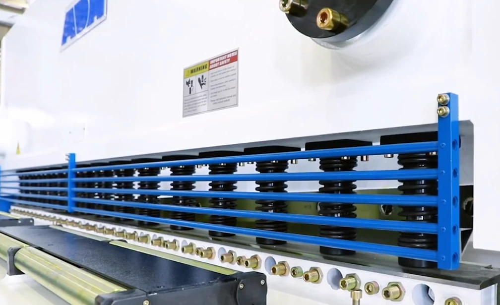
Use the trial cut to choose what to check—not to guess an adjustment. Record the material grade and thickness, current settings, and whether defects occur along the whole cut or only in particular areas. These observations help connect the result to blade condition, setup, and sheet control.
Read the edge: rollover, smooth burnish, rougher fracture zone, and exit burr
Inspect the safely retrieved edge from the blade-entry side toward the exit side. A typical sheared edge shows:
| Feature | Description |
|---|---|
| Rollover | The rounded entry corner where metal initially deformed. |
| Smooth burnish | The smoother band formed by blade penetration and sliding contact. |
| Rougher fracture zone | The textured surface left as cracks completed separation. |
| Exit burr | The thin, sharp projection remaining at the exit edge. |
Their proportions vary with material and cutting conditions. A rough fracture zone is expected; a wider burnished band is not automatically better. Judge the edge against the job’s requirements rather than an assumed ideal appearance, and do not run fingers along it to assess sharpness.
Excessive burrs or abnormal roughness: check clearance, blade wear, and material behavior
Large burrs, especially with pronounced rollover or an unusually rough or angled fracture face, suggest checking blade clearance and cutting-edge condition. Excessive clearance lets more metal deform before separation; worn or dull edges can also increase deformation and leave larger burrs. Appearance alone cannot distinguish these causes.
Confirm the actual material and thickness, compare clearance with the approved material-specific setting, and have blade wear or damage checked through the approved inspection procedure. Material behavior also affects the result: metal that deforms more before fracturing may produce a different edge from less ductile stock at the same thickness. Do not reduce clearance solely because the burr looks large.
Secondary shearing or double burnishing: check whether clearance is too tight
An extra smooth band or a crushed-looking, doubled burnished region can indicate secondary shearing—additional shearing after the initial crack paths fail to meet cleanly. Too-tight clearance is a likely cause because it can prolong compression and blade contact, increasing cutting force and wear.
Check the actual gap against the approved setting before changing it. A doubled band is evidence to investigate, not proof of a particular gap error. If it accompanies unusual loading, stop and follow the capacity and condition checks below rather than making another trial cut.
Bowing, twisting, or camber: check rake, strip width, support, clamping, and alignment
Separate the shape defects before troubleshooting: bow is lengthwise bending out of the intended plane; twist rotates the strip along its length; camber is sideways curvature within its plane. These defects can occur even when the cut face looks acceptable.
Check rake together with strip width. Greater rake spreads engagement along the cut and generally reduces peak cutting force, but it can increase distortion, particularly in narrow strips that resist bending and twisting less effectively. Also check whether supports keep the sheet properly seated, hold-downs prevent movement, and machine alignment is correct. Changing clearance alone will not correct inadequate support or restraint.
Wrong dimensions or out-of-square cuts: check backgauge position, squaring, and sheet movement
First confirm the backgauge position—the stop that establishes cut length—and whether the sheet seated against it correctly. Then check the squaring guide and sheet restraint. A correct gauge setting cannot produce a reliable dimension if the sheet sits crookedly or moves during the stroke.
Measure the specified dimension at more than one relevant position and check squareness with the approved measuring method. A consistent length offset suggests checking the gauge setting or reference; a dimension that changes across the part suggests checking squaring, seating, and movement. These patterns guide inspection but do not establish a unique cause.
Incomplete separation or unusual loading: stop and check capacity, settings, and blade condition
Stop the process if the sheet does not separate fully or the machine shows unusual loading. Do not repeat the stroke merely to see whether the cut finishes, or pull at a partly attached piece.
Follow the approved stop, inspection, and energy-isolation procedures before accessing the hazard area or inspecting blades. Have capacity checked for the actual material strength, thickness, and cut length, then verify settings and blade condition. Incorrect settings, overload, and damaged blades require different corrections; a setting change does not make an over-capacity job acceptable.
After approved corrections, verify dimensions, squareness, burrs, and flatness before production
Resolve unsafe conditions before another trial. For controlled quality adjustments, change one approved setting at a time where practical and record it, so the next result can be linked to that change.
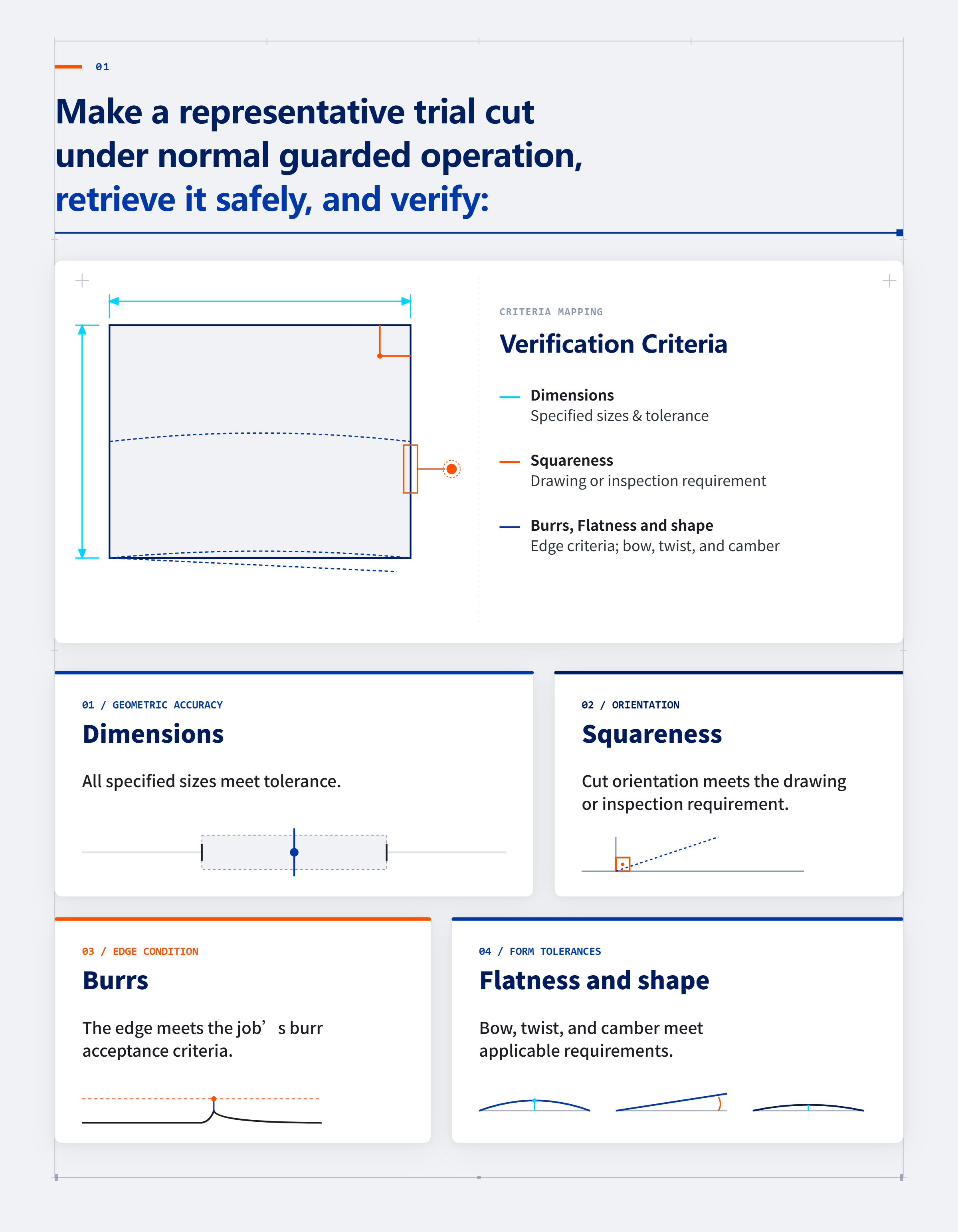
Make a representative trial cut under normal guarded operation, retrieve it safely, and verify:
- Dimensions: all specified sizes meet tolerance.
- Squareness: cut orientation meets the drawing or inspection requirement.
- Burrs: the edge meets the job’s burr acceptance criteria.
- Flatness and shape: bow, twist, and camber meet applicable requirements.
Release the setup for production only when these checks pass and any abnormal separation or loading has been resolved. A better-looking edge is evidence of improvement—not, by itself, proof that the part or process is acceptable.