
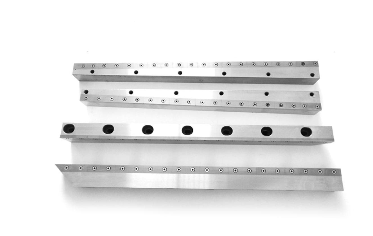
Clean Cuts Require More Than Sharp Blades That Fit
A sharp blade that bolts into place can still produce poor cuts—or suffer damage—if its material, geometry, or setup is wrong for the machine and sheet. Reliable shearing depends on a matched cutting system: the machine, upper and lower blades, workpiece, and blade settings must work together. Physical fit is necessary, but it does not establish cutting suitability.
How Upper and Lower Blades Shear Sheet Metal—and Why Hydraulic Power Does Not Determine Blade Grade
Shear blades are the upper and lower cutting tools that separate sheet metal through localized deformation and fracture. In a typical sheet-metal shear, the upper blade presses into the sheet while the lower blade supports it. As the blades pass each other with a controlled gap, the metal deforms and cracks develop from the two cutting edges. Those fracture paths must meet through the sheet’s thickness for controlled separation.
That gap matters because shearing is not simply slicing through metal with a sharp edge. The sheet must deform enough to fracture without excessive bending or tearing. Incorrect blade spacing can disrupt that process even when both edges are sharp.
Hydraulic power supplies the force that drives the cutting stroke; it does not, by itself, determine the required blade steel. Blade grade must suit the work material, cutting duty, and machine design. The edge needs wear resistance, but it also needs enough toughness to resist chipping under the expected load. Available hydraulic force cannot compensate for an unsuitable blade grade or make a cut outside the machine’s rated capacity acceptable.
How Machine Design, Workpiece Strength, Blade Geometry, Clearance, and Edge Condition Work Together
Each part of the setup affects either how the sheet fractures or how the blade carries the cutting load:
- Machine design and blade geometry: The machine determines the blade path and support. The blade’s cutting-edge angle affects edge strength and cutting force. Separately, the machine’s rake angle—the inclination of one blade relative to the other along the cut—affects how much sheet is engaged at once. These features must suit the application, not merely the mounting space.
- Workpiece properties: Thickness and strength affect the required cutting force. Ductility, meaning how much the metal can deform before breaking, affects how it separates. A setting that cuts one material well may produce excessive deformation or poor fracture in another.
- Clearance: This is the horizontal gap between the cutting edges as they pass. Too little clearance can increase friction and wear; too much can encourage burrs and edge deformation. Use the manufacturer’s specifications for the material and thickness rather than treating one gap as suitable for every job.
- Alignment: This describes the blades’ positional relationship along the machine. A correct clearance at one location does not prove the setup is correct across the cutting length.
- Edge condition: Dull, chipped, or otherwise damaged edges change how the sheet is loaded and separated. They can worsen finish even when the other settings are correct.
These interactions make cut defects clues, not proof of dullness. A burr may justify checking clearance as well as inspecting the edge; sharpening alone will not correct misalignment or an unsuitable blade.
Before comparing blade grades or prices, verify the machine’s blade requirements and the intended work material and thickness. That compatibility check establishes which blades are candidates at all.
Choose Compatible Blades With This Buying Checklist
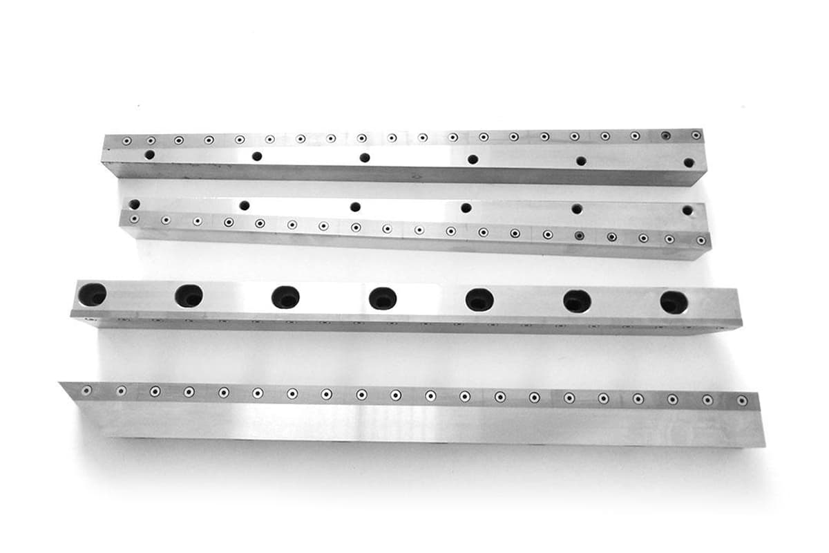
Work through these checks in order: establish machine compatibility, document the application, then compare blade materials and lifetime cost. Buy only blades approved for the machine and intended work. Matching length and bolt holes alone does not establish compatibility.
Confirm the Machine Model, Shear Design, and Rated Capacity for Your Material and Cutting Length
Record the exact machine model, serial number, shear design, and approved blade part numbers. Check the machine documentation for its blade arrangement, beam design, and operating limits rather than ordering from nominal blade size. For product information on CNC shearing equipment, consult the ADH Machine Tool brochures, then verify blade requirements against the documentation for your specific machine.
Verify rated capacity against the actual material grade and strength, thickness, and cutting length. A thickness rating based on one material strength does not establish capacity for a stronger sheet. Check that the intended production rate also falls within the machine’s duty limits. If those requirements exceed the current machine’s limits, compare ADH Machine Tool’s CNC shearing machines as a potential equipment option rather than relying on a different blade grade.
If the documentation does not cover your workpiece or cut length, obtain confirmation from the machine manufacturer before ordering. For an ADH Machine Tool machine, contact its sales and service team to discuss your application and request confirmation; its network includes more than 50 sales and service points in China and overseas. A different blade grade does not increase the machine’s rated capacity.
Verify Blade Dimensions, Bevels, Hole Centers, Countersinks, and Mounting Orientation Against the Approved Drawing
Give the supplier the current blade drawing approved for your machine, and require confirmation of:
- Overall dimensions: length, width, thickness, and their tolerances.
- Cutting geometry: bevel angle and direction—the angle and orientation of any sloped cutting face.
- Mounting holes: hole pattern, diameters, and center-to-center spacing.
- Countersinks: the angled recesses for fastener heads, including their dimensions and location.
- Orientation: which face seats against the holder and which edge occupies the cutting position.
These details determine seating and cutting-edge position, not merely whether bolts can enter the holes. Incorrect countersink depth can interfere with fastening; a reversed bevel can place the wrong geometry at the cut.
Use measurements from an existing blade as a cross-check, not as the sole specification: wear or previous regrinding may have changed its dimensions. Resolve drawing discrepancies before placing the order.
Match Upper and Lower Blade Configurations: Single-Edge, Reversible, and One-Piece or Segmented Designs
Identify the upper and lower positions separately on the purchase order. Similar-looking blades are not necessarily interchangeable, and replacing one position does not justify changing its specified geometry.
Confirm the approved arrangement:
- Single-edge or reversible: A reversible blade offers additional cutting edges only in its permitted orientations. Ask how many edges are actually usable in each mounting position; do not count every corner as a cutting edge.
- One-piece or segmented: A one-piece blade spans its specified length continuously; a segmented arrangement uses separate sections. Segments can make handling and local replacement easier where permitted, but their positions and joints must match the machine design.
- Individual blade or matched set: Confirm whether one blade or segment may be replaced independently and what dimensional relationship must be maintained with the remaining blades.
Treat these as machine-specific configurations, not optional upgrades selected solely for convenience.
Give the Supplier Your Material Grades, Thickness Range, Production Volume, and Cut-Quality Requirements
Send a written application summary with the machine details and approved drawing. Include:
- Workpiece specifications: material grades and specified strength, not just broad descriptions such as “steel” or “stainless.”
- Working range: minimum and maximum thickness, longest cut, and the combinations used most often.
- Production duty: expected cuts per shift, frequency of continuous runs, and whether work consists mainly of short batches.
- Quality requirements: acceptable burr, edge deformation, straightness, and dimensional tolerance, using drawing requirements or representative samples where available.
- Relevant service history: the current blade grade, known wear or chipping patterns, and any unresolved setup problems.
This information lets the supplier distinguish gradual edge wear from a need for greater resistance to chipping. High production volume may make wear resistance more valuable, but volume alone does not identify the right steel. Ask the supplier to explain why the proposed grade and heat treatment suit your work mix within the machine’s approved options.
Blade-Material Comparison Table: Steel Family, Typical Applications, Wear Resistance, Toughness, and Limitations
Wear resistance describes resistance to gradual material loss from the edge. Toughness describes resistance to cracking and chipping under load. A blade needs an appropriate balance; improving one property does not guarantee better overall service.
Compare Alloy Tool Steels, High-Chromium Tool Steels, and Manufacturer-Specified Specialty Grades
These are broad supplier descriptions, not mutually exclusive steel classifications: high-chromium tool steels are also alloy tool steels. The comparisons below describe selection tendencies, not guaranteed properties.
| Steel family or supplier category | Typical applications | Relative wear resistance | Relative toughness | Main limitations |
|---|---|---|---|---|
| Alloy tool steels selected for toughness | General shearing or work where chipping resistance receives priority | Often lower than wear-focused high-chromium grades | Often higher when grade and heat treatment favor toughness | May wear sooner in demanding repetitive work; the family name alone says little about performance |
| High-chromium tool steels, including high-carbon high-chromium grades | Repetitive cutting where gradual wear is the main life limit | Often high | Can be lower than toughness-focused alternatives | Chipping may limit life before wear does if loading or setup is unsuitable |
| Manufacturer-specified specialty grades | Particular workpieces or duties covered by the machine’s approval | Grade-dependent | Grade-dependent | “Specialty” is not a performance ranking; require an exact grade and application-specific justification |
Choose between documented grades, not family labels. Machine approval, heat treatment, and the specified hardness range carry more decision value than a claim that one steel family is universally best.
Weigh Heat Treatment and Resistance to Chipping Against Wear Resistance—not Hardness Alone
Hardness measures resistance to localized indentation; it does not by itself establish toughness or predict blade life. A harder edge may resist wear yet chip sooner if its toughness is insufficient for the cutting load. Incorrect clearance or misalignment can also damage an otherwise suitable blade, so a material upgrade is not a setup correction.
Request the exact steel designation, specified hardness range, and heat-treatment documentation, including the quench-and-temper condition where applicable. Ask for a material certificate or analysis report and records traceable to the supplied blades.
These documents support grade identification and processing consistency. They do not replace machine approval or prove a particular service life: the same nominal grade can behave differently when its heat treatment differs.
Compare Lifetime Cost: Usable Edges, Regrinding Allowance, Replacement Availability, and Downtime
Compare approved candidates over the same expected workload, not just by purchase price.
- Usable edges: Count only edges permitted in the intended mounting positions. Additional usable edges can reduce replacement purchases, but turning a blade still requires labor and setup.
- Permitted regrinding: Regrinding removes steel to restore the edge. Obtain the approved minimum finished dimensions, permitted material removal, and any required setup compensation. Do not assume every blade can be reground indefinitely—or at all.
- Replacement availability: Check lead times for the exact grade and configuration, including whether individual segments or blades remain available.
- Downtime and service costs: Include grinding charges, shipping, changeover labor, setup checks, and lost production. Compare life claims cautiously unless records from comparable work support them.
A lower purchase price is not necessarily a lower lifetime cost, and a more wear-resistant steel is not automatically worth its premium. Favor the approved option with a documented fit to the work and a practical replacement and servicing plan.
Purchase compatibility does not establish operating readiness. Before cutting, even an approved blade pair needs correct seating, clearance, and alignment to the manufacturer’s specifications.
Set Clearance and Alignment Using the Machine’s Specifications
Correct setup makes the two cutting edges work as a pair. Clearance must suit the workpiece material and thickness, and it must remain within the machine’s specified limits along the cutting length. A sharper edge cannot compensate for incorrect spacing or alignment.
Before Hands-On Checks: Lock Out Energy, Control Stored Hydraulic Pressure, and Secure the Ram
Only authorized, qualified personnel should perform hands-on setup checks. They must follow the machine manual and site procedure for isolating and locking out energy, verifying isolation, controlling stored hydraulic pressure, and securing the ram—the moving assembly that carries the upper blade.
Turning off the main power does not necessarily remove stored energy. Trapped hydraulic pressure can still cause movement, and the ram’s weight remains a hazard. Do not rely on hydraulic pressure to hold it up. Use the manufacturer-approved ram-securing provisions and sequence before entering a danger area.
These are safety requirements, not a universal lockout procedure. If the machine-specific instructions or approved securing equipment are unavailable, stop and obtain them before proceeding.
Distinguish Blade Clearance From Rake Angle, Overlap, and Backgauge Position
These settings control different parts of the cut:
- Blade clearance is the lateral gap between the upper and lower cutting edges as they pass one another.
- Rake angle is the upper blade’s inclination along the cutting length. It determines how progressively the blade engages the sheet; it is not the blade’s sharpened edge angle.
- Blade overlap is how far the moving cutting edge passes the fixed edge in the cutting direction. It is not the lateral gap.
- Backgauge position sets the sheet’s stopping position for a repeatable cut width. It does not set blade clearance.
During shearing, the edges first deform and penetrate the sheet. Fractures then develop from the opposing cutting zones. Clearance affects whether those fractures meet cleanly. Excessive clearance allows more bending before separation, which can leave a rolled or torn edge. Insufficient clearance can force additional shearing and raise cutting loads.
Moving the backgauge may correct cut width, but it cannot correct that fracture mechanism. Likewise, changing overlap or rake is not a substitute for setting clearance.
Use the Manufacturer’s Material-and-Thickness Clearance Chart, Not a Universal Percentage
Identify the actual material grade and thickness, then use the machine manufacturer’s applicable clearance chart. Include hardness or material condition where the chart distinguishes them: materials that resist deformation or fracture differently do not necessarily require the same gap at the same thickness.
A percentage of thickness is not a complete setup specification. It does not establish whether the setting suits that material, blade arrangement, or machine. If the chart does not cover the workpiece, obtain manufacturer guidance rather than extending a nearby entry by guesswork.
Treat the chart value or range as the required target, not as proof that the blades have reached it. The next check must establish the actual clearance using the prescribed measuring method.
Have Qualified Personnel Check Blade Seating, Specified Alignment, and Clearance Along the Cutting Length
With the required safety controls in place, qualified personnel should follow the manufacturer’s procedure to verify:
- Blade seating: The blades rest correctly against their mounting surfaces. Trapped debris, damaged seating surfaces, or incorrect mounting can shift an edge even when the blade itself is suitable.
- Specified alignment: The blades and supporting assemblies meet the machine’s stated alignment requirements. Do not substitute an assumed “perfectly parallel” arrangement for the specified geometry.
- Clearance along the cutting length: Measurements at the prescribed positions meet the required limits—not merely the reading at the center.
A satisfactory center reading can hide a tight end. That end then cuts under different conditions, creating uneven loading and potentially uneven wear or edge quality. Do not average acceptable and unacceptable readings: an average does not remove the local interference or excessive gap.
Correct discrepancies through the prescribed seating or alignment procedure, then recheck. Persistent side-to-side differences warrant investigation of blade or beam position rather than an automatic decision to sharpen the blades.
Verify Adjustable Rake, Hold-Downs, and Sheet Support; Restore Guards Before Test Cutting
After clearance and alignment are established, check the remaining controls that affect how the sheet moves through the cut:
- Adjustable rake, where provided: Use the specified setting for the application. Rake changes how much blade length engages at once, affecting load distribution and workpiece deformation. Do not attempt to alter a fixed-rake machine.
- Hold-downs: Verify their condition and operation by the approved procedure. They restrain the sheet during cutting; inadequate restraint allows movement that can undermine dimensional consistency.
- Sheet support: Confirm suitable support for the sheet and cut piece. Unsupported material can sag or rotate, adding bending that clearance adjustment alone cannot eliminate.
Restore guards and protective devices before test cutting, and follow the approved return-to-service procedure. Use a controlled test cut in the intended material and thickness, within machine capacity, to assess edge quality, straightness, distortion, and the dimension set by the backgauge.
If the result is unsatisfactory, treat the defect as evidence to investigate. Clearance, rake, hold-down action, and support remain diagnostic variables—not reasons to declare the blade dull without further checks.
Diagnose Poor Cuts Before Sharpening or Buying Blades
A burr is a clue, not a diagnosis. Check the material, specified setup, and edge condition before deciding that sharpening or replacement is the remedy. The useful evidence is not just what the defect looks like, but where it occurs, when it began, and whether the workpiece or setup changed.
Troubleshooting Table: Cut Defect, Possible Causes, Safe Checks, and Corrective Action
Use this table to identify checks—not to diagnose a blade from a single symptom. Record the actual material grade and thickness, the defect’s location, and any recent setup changes.
Keep observation separate from intervention:
- Piece checks: Examine completed test pieces only after safe removal under the approved procedure, away from the cutting zone. Handle them as sharp-edged material.
- Isolated checks: Blade inspection, gap measurement, mounting checks, and other hands-on machine work require qualified personnel and the isolation precautions established earlier: isolate energy, control stored pressure, secure the ram, and verify isolation.
- Powered checks: Where the manufacturer requires a powered functional check, follow its guarded procedure. Restore guards and complete the approved return-to-service procedure before test cutting.
If any stop condition listed below is present, do not make another test cut.
| Cut defect | Possible causes—not proof | Safe checks | Corrective action |
|---|---|---|---|
| Excessive burrs | Excessive clearance; rounded or worn edges; material grade, hardness, or thickness unsuitable for the current setup | Piece: Confirm stock identity and thickness; note whether burrs cover the whole cut or only part. Isolated: Inspect edge condition and measure clearance at the prescribed positions along the cutting length. | Restore the specified clearance for the actual stock or use suitable material. Consider edge servicing only when inspection confirms deterioration. |
| Rough or torn edges | Clearance too wide or too tight; edge wear; material variation or mismatch | Piece: Compare with an acceptable piece of the same material and thickness, if available. Isolated: Verify clearance and inspect the cutting edges. | Correct measured deviations using the manufacturer’s procedure. Do not choose whether to open or close the gap from surface appearance alone. |
| Inconsistent quality along the cut | Local edge damage; poor blade seating; alignment error; machine wear; uneven hold-down action | Piece: Map the defect to its position along the machine. Isolated: Check corresponding blade sections, seating surfaces, fastenings, specified alignment, and hold-down condition. | Correct approved seating or alignment faults. Damage or loose mountings trigger the stop procedure below; persistent local defects require qualified diagnosis. |
| Bow, twist, or other distortion | Excessive rake for the application; insufficient restraint or support; material variation | Piece: Note which piece distorts and its width and orientation. Check support arrangements without entering the hazard zone; assess hold-down operation only by the approved procedure. | Restore specified adjustable rake, restraint, and support. Do not attempt to alter fixed rake or assume a sharper blade will remove distortion. |
| Dimensional variation | Incorrect backgauge setting; poor gauge repeatability; inconsistent sheet seating; slipping under hold-downs; inadequate support | Piece: Measure from the same reference edge each time and distinguish a constant error from changing dimensions. Check gauge settings; use approved isolated or guarded procedures for mechanical and functional checks. | Correct the approved gauge setting and sheet-positioning method. Address restraint or support faults; refer unresolved repeatability problems to a technician. |
Heavy Burrs, Tearing, or Rough Edges: Check Clearance, Edge Wear, and Material Suitability
The timing helps separate competing explanations. A defect that starts immediately after a stock change directs attention to the new material and its required setup. Burrs that grow gradually under a verified, unchanged setup make edge wear a stronger suspect—but still do not prove it.
Clearance symptoms overlap: an excessive gap can permit more bending and tearing, while an insufficient gap can cause additional shearing and rough fracture. The next decision should follow the measured clearance and inspected edge condition, not a rule such as “more burr means close the gap.”
Uneven Quality Along the Cut: Check Local Damage, Blade Seating, Alignment, and Machine Wear
When comparing completed pieces, record which end corresponded to each side of the machine. A defect that repeatedly appears at the same machine position points toward a local cause worth investigating: an edge defect, seating problem, alignment discrepancy, or uneven restraint.
This location map gives the technician a useful starting point. It does not establish that the blade itself is faulty; sharpening cannot remove debris behind a blade or correct wear in a supporting assembly.
Bow, Twist, or Incorrect Dimensions: Check Rake, Hold-Downs, Sheet Support, and Backgauge Settings
Separate shape error from positioning error before moving the backgauge. A bowed or twisted piece can make dimensional assessment misleading, so check flatness and use the prescribed measurement method.
A consistent width offset directs attention toward the gauge setting and reference edge. Widths that change between otherwise comparable cuts also warrant checks for inconsistent seating, sheet movement, or gauge repeatability. Rake affects deformation during separation; the backgauge sets the stopping position. Changing one to compensate for a fault in the other can conceal the cause without producing a stable process.
Stop Cutting for Cracks, Chipping, Loose Mountings, Suspected Blade Contact, or Abnormal Noise
Stop cutting immediately if any of these conditions appears. They indicate possible damage or instability, not merely an unacceptable finish. Continued operation can worsen blade damage and increase safety risk.
Follow the machine’s approved stopping and isolation procedure and keep it out of service pending qualified assessment. Do not make a confirming cut, reach into the cutting zone, or attempt an adjustment while the machine remains capable of movement. Do not assume that tightening a mounting or removing a chipped edge resolves the underlying cause.
Return the machine to service only after qualified personnel have assessed the damage, corrected the cause, confirmed serviceability, and completed the approved return-to-service procedure.
Escalate Persistent Defects to a Qualified Technician Rather Than Repeatedly Replacing Blades
Escalate when defects remain after approved corrections, return quickly, or accompany signs of worn or unstable machine components. Repeated blade changes cannot correct faults in guides, beds, fastenings, or hold-down mechanisms.
Give the technician the material specification and thickness, blade identification, measured settings, defect-location notes, and representative completed pieces. Record what was corrected and how the result changed. That evidence helps distinguish a recurring setup or machine fault from genuine edge deterioration.
Once diagnosis separates those causes, use the blade’s condition and manufacturer service limits to choose maintenance, rotation to an approved unused edge, regrinding, or replacement. The decision should follow the condition assessment—not the first poor cut.
Maintain Blades and Decide When to Rotate, Regrind, or Replace
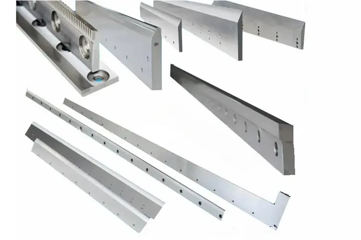
Choose service from the blade’s confirmed condition and manufacturer limits—not a promised lifespan. Rotation and regrinding are options only while the blade remains serviceable within its approved geometry and dimensions. Neither can make a cracked, severely damaged, undersized, or incompatible blade acceptable.
Set Inspection Intervals From Workload, Material, and Cut-Quality Trends
Start with the manufacturer’s required checks, then increase inspection frequency when operating conditions warrant it. More cutting cycles, harder or more abrasive stock within the machine’s rating, and worsening cut-quality trends can justify shorter intervals. A calendar alone does not distinguish a lightly used machine from one cutting throughout a shift.
Use recorded burr growth, edge rounding, and other wear indicators to schedule checks before quality becomes unacceptable. Compare similar materials and settings so that a change in the work does not masquerade as faster blade wear. Abnormal noise, chipping, or other previously identified stop conditions require immediate action, not an earlier appointment on the maintenance schedule.
Under Safe Isolation, Remove Debris, Inspect Edges and Fasteners, and Apply Approved Corrosion Protection
Perform cleaning and inspection only under the established isolation procedure, including lockout, control of stored energy, and securing components against movement. A stopped machine is not necessarily isolated.
- Clean: Use approved tools and cleaning products to remove chips, debris, and oil buildup from accessible areas. Do not sweep sharp edges with bare hands or loosen a blade merely to reach behind it; removal requires the controlled procedure.
- Inspect: Examine cutting edges for rounding, chips, cracks, and deformation. Check accessible blade seats and fasteners for contamination, damage, and signs of looseness. Refer suspect mountings for qualified assessment rather than assuming tightening alone resolves the problem.
- Protect: Apply only approved corrosion protection to the specified surfaces. Keep residues off clamping faces or other areas where they could interfere with seating, alignment, or cutting unless the manufacturer expressly permits them.
Cleaning makes defects easier to see; it does not establish that a damaged blade is safe to return to service.
Rotate Only Approved Reversible Blades With Sound, Unused Edges
A reversible blade is designed to be repositioned to expose another cutting edge. Confirm that the exact blade design permits rotation and identify the allowed orientation; a rectangular shape or apparently sharp corner is not sufficient evidence.
Inspect the whole blade, not just the proposed working edge. Rotate only when the unused edge is sound and the blade has no cracks, chips, deformation, or other damage that rules out rotation. Turning damage away from the cut does not remove it from the blade.
Track which edges have been used. Rotation can expose a fresh edge without grinding away material, but it still requires the applicable removal, installation, and setup checks.
Use Specialist Regrinding Within the Specified Edge Geometry and Minimum Blade Dimensions
Regrinding removes material to restore the cutting edge. Send the blade to a specialist with the manufacturer’s drawing or service instructions, including approved grinding faces, edge geometry, minimum dimensions, and permitted material-removal allowance.
The specialist must measure the blade and determine whether the required grind will leave it within all service limits. A keen edge is not enough if the finished blade no longer has the dimensions needed for correct clamping and positioning. Do not authorize grinding based on appearance or an assumed number of remaining regrinds.
Grinding direction and permitted faces depend on the design; do not assume that reducing blade height or changing the profile is acceptable. If the limits are unavailable, obtain them before approving the work. Using every reversible edge does not automatically require replacement: a compliant regrind may still be possible.
Restore Blade Position After Regrinding Only With Manufacturer-Approved Adjustment or Shimming
Material removed during grinding can change where the cutting edge sits relative to its mounting and the opposing blade. Restoring sharpness therefore does not automatically restore the original setup.
Qualified personnel should use the finished blade dimensions to determine whether the manufacturer requires an adjustment or permits shims—specified spacers used to establish position. Use only the approved arrangement; do not stack improvised packing behind a blade or alter its seat to compensate for excessive material loss.
After mounting, verify seating, fastening, clearance, parallelism, and any other geometry required by the machine instructions. If correct positioning cannot be achieved within the approved adjustment range, the blade cannot return to service.
Replace Cracked, Severely Damaged, Undersized, or Incompatible Blades
Replace blades with cracks, severe chipping or deformation, dimensions below the permitted minimum, or incompatibility with the machine or application. Keep damaged blades out of service during assessment, and clearly identify rejected blades so they cannot be mistaken for usable spares.
Replacement is also justified when wear cannot be removed by a permitted regrind or when no approved service option remains. Persistent poor cuts alone are not sufficient grounds: unresolved seating, setup, or machine faults can damage the replacement or reproduce the same defect.
Do not use shimming, rotation, or further grinding to bypass a rejection limit.
Record Cutting Conditions, Edge Changes, Regrinds, and Recurring Defects to Track Service Life
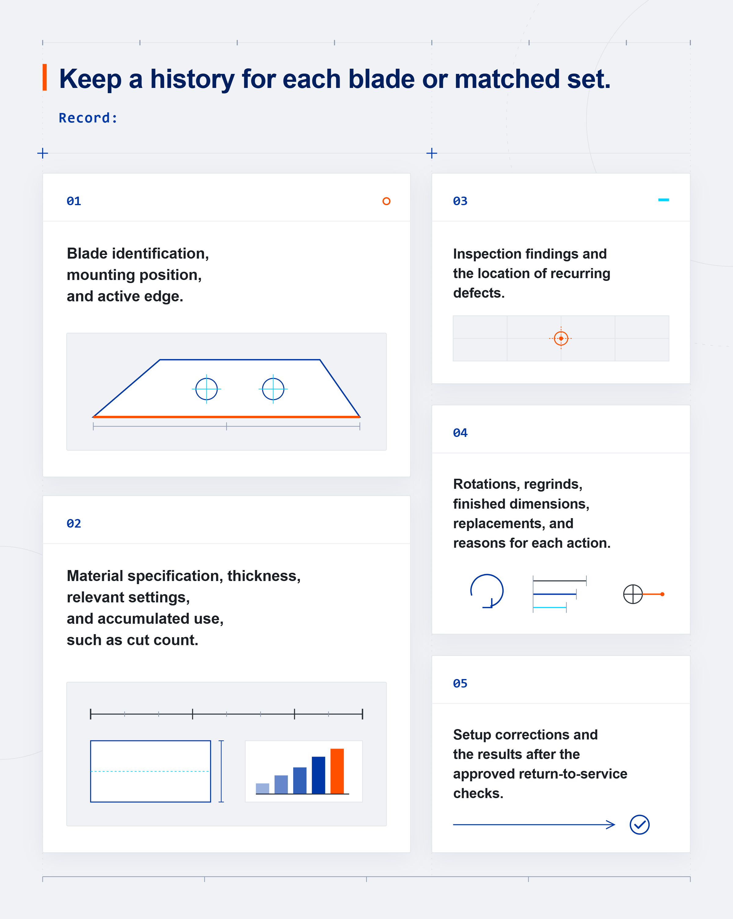
Keep a history for each blade or matched set. Record:
- Blade identification, mounting position, and active edge.
- Material specification, thickness, relevant settings, and accumulated use, such as cut count.
- Inspection findings and the location of recurring defects.
- Rotations, regrinds, finished dimensions, replacements, and reasons for each action.
- Setup corrections and the results after the approved return-to-service checks.
These records help distinguish normal wear from recurring faults and support inspection intervals and purchasing decisions based on comparable work. They show service trends, not a guaranteed future lifespan.
Once replacement is justified, proceed to controlled removal, installation, and verification. Rotated and reground blades also need the applicable installation checks before cutting resumes.
Replace Blades Safely and Verify Cut Quality Before Production
Blade replacement is complete only when the machine passes its prescribed setup and safety checks and representative cuts meet the job’s requirements. Use this checklist as a high-level guide for qualified personnel—not as a substitute for the machine’s service procedure.
Prepare the Approved Blades, Service Instructions, Handling Equipment, and Qualified Personnel
Before taking the machine out of service, confirm that the following are ready:
- Approved replacement blades: Verify their identification, condition, mounting orientation, and documented suitability for the machine and intended work.
- Machine-specific service instructions: Have the removal, installation, setup, and return-to-service requirements available, including fastening specifications.
- Suitable handling equipment: Prepare equipment and blade supports appropriate to the blade’s weight, shape, and approved lifting method. Plan a stable place for the removed blade.
- Qualified personnel: Assign people trained and authorized for the isolation, handling, installation, and verification tasks, with the staffing required by the procedure.
If blade approval, handling arrangements, or service specifications are missing, resolve the gap before starting removal.
Lock Out the Machine, Secure the Ram, and Support Each Blade Before Releasing Its Fasteners
Follow the manufacturer’s specified sequence for placing the ram—the moving upper blade carrier—in its safe service position, isolating and locking out relevant energy sources, controlling stored hydraulic or pneumatic pressure, and securing the ram with approved supports. Verify isolation and securement before anyone enters the cutting zone. Shutting off the controls alone does not control stored pressure or prevent gravity-driven movement.
Support each heavy, sharp blade with the approved handling arrangement before loosening its fasteners. Ram securement and blade support serve different purposes: securing the carrier does not necessarily retain a blade once its mounting bolts are released.
Remove guards or accessories only as the service procedure requires. Protect wires, sensors, and other linked components from contact or strain during removal.
Clean and Inspect Mounting Seats, Then Install With the Specified Fasteners, Tightening Sequence, and Torque
Clean the mounting seats—the surfaces that locate and support the blade—and inspect them for burrs, contamination, damage, and uneven wear. Material trapped behind a blade can prevent full seating and change its alignment. Have suspect seats assessed and corrected through the approved procedure before installation.
Install the blade in its specified orientation using the required fasteners. Follow the manufacturer’s tightening sequence and torque values with the specified torque tool; neither “tight by feel” nor a generic bolt chart establishes correct blade clamping. Keep the blade supported until the procedure permits removal of its handling equipment.
Reset Clearance and Alignment, Restore Safeguards, and Complete the Manufacturer’s Commissioning Checks
Use the checks described in the setup section to restore clearance and alignment to the manufacturer’s requirements for the actual material and thickness. Verify them at the prescribed locations; a newly installed blade does not establish correct setup by itself.
Follow the manual’s return-to-service sequence for removing tools, handling equipment, and temporary supports; reconnecting disturbed components; restoring guards and safety devices; and releasing isolation. These actions must occur in the approved order, not as an improvised cleanup step.
Complete the prescribed commissioning checks—the safety, functional, and setup checks required before operation. Any failed safety check blocks test cutting as well as production.
Approve Representative Test Cuts for Burrs, Edge Consistency, Distortion, and Dimensions
Once the machine is cleared for test cutting, use scrap or sample stock representative of the production material, thickness, and relevant cut conditions. Make the cuts under the approved guarded operating procedure. A satisfactory cut on easier or thinner stock does not verify the intended job.
Compare the samples with the drawing and job acceptance requirements:
- Burrs: Check the raised metal along the cut edge against the permitted burr limits.
- Edge consistency: Inspect the full cut for unacceptable changes in finish, tearing, or localized defects.
- Distortion: Check bowing, twisting, or other deformation against the job’s limits.
- Dimensions: Measure finished size, straightness, and squareness as required.
Record the verified settings and test-cut results, and obtain the required release approval before production resumes. If a quality requirement remains unmet, keep the machine out of production and return to diagnosis rather than assuming another blade change will solve it.
I. Introduction
Hydraulic shearing machines are essential tools in various industrial settings, specifically used for cutting sheet metal with precision and efficiency. These machines are a cornerstone used in sheet metal fabrication shops, automotive industries, and manufacturing units. Central to their operation are the shear blades, which play a critical role in determining the accuracy and quality of the cutting.
Shear blades in hydraulic shearing machines slice through metals with minimal deformation. This ensures clean and precise cuts every time. The choice of shear blade directly impacts the machine’s performance, the longevity of the blade, and the quality of the finished product.
Selecting the appropriate type of shear blade is crucial for optimizing operational efficiency and achieving desired results. Additionally, understanding maintenance needs and operational costs associated with different types of blades is vital for long-term operation.
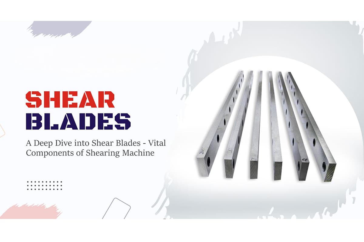
This article provides an overview of the various types of shear blades used in hydraulic shearing machines. We will delve into their descriptions, functionalities, and common applications, and discuss their advantages and disadvantages to help you make informed decisions about hydraulic shearing machine blades.
II. Types of Shear Blades
2.1 Blade Material -Based Classification
If blade geometry determines how you cut, blade material defines what you can cut—and how long you can keep cutting. This is not only a contest in materials science but also a strategic trade-off between hardness, toughness, wear resistance, and cost.
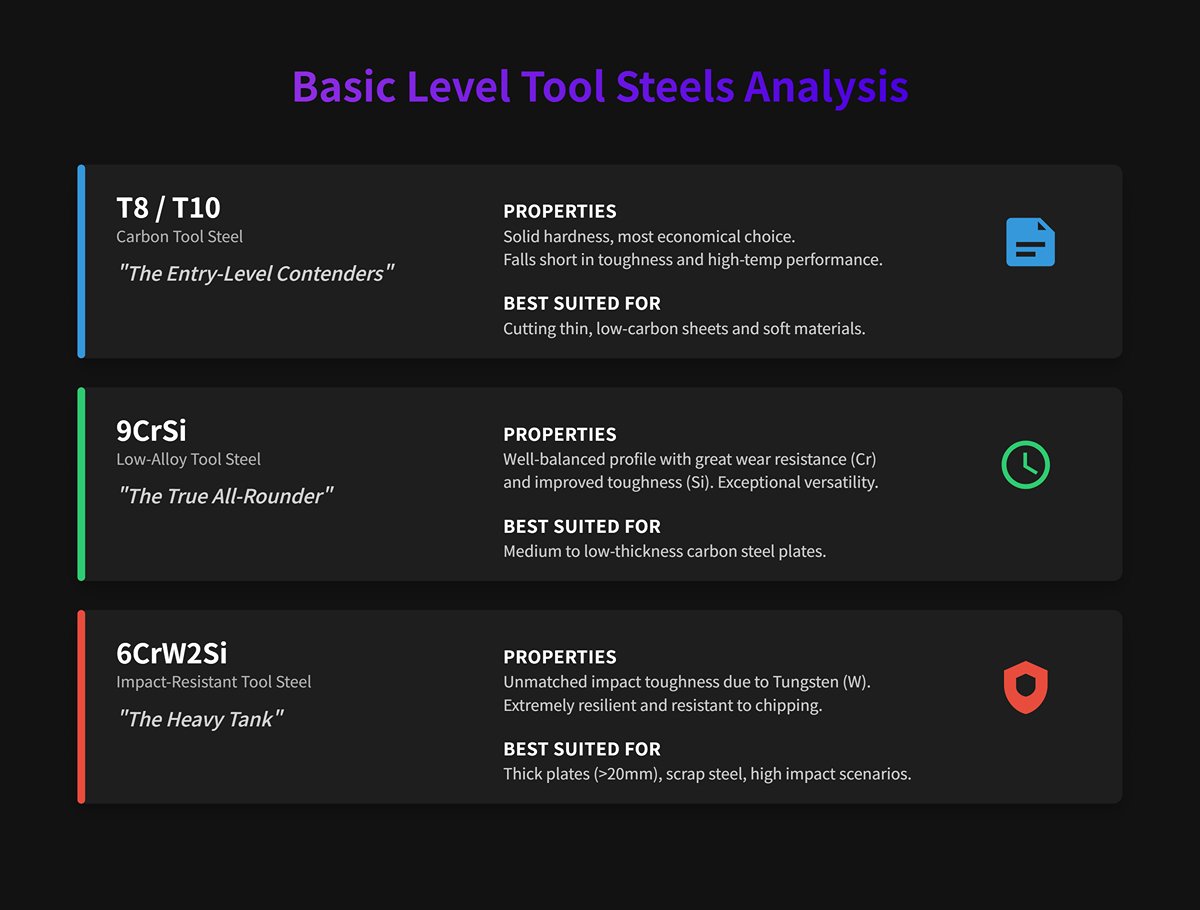
- Basic Level (Carbon/Alloy Tool Steels): The King of Value
- T8 / T10 (Carbon Tool Steel): The “entry-level contenders” of the blade world. They offer solid hardness but fall short in toughness and high-temperature performance (red hardness). The most economical option, best suited for cutting low-carbon thin sheets and soft materials like aluminum—easy targets.
- 9CrSi (Low-Alloy Tool Steel): The undisputed industry benchmark. Chromium (Cr) increases wear resistance, while silicon (Si) improves toughness, resulting in a well-balanced performance profile. A true all-rounder for medium- to low-thickness carbon steel plates, dominating the market with its exceptional versatility and cost-effectiveness.
- 6CrW2Si (Impact-Resistant Tool Steel): The “heavy tank” among blades. Tungsten (W) imparts unmatched impact toughness. Not the hardest, but unquestionably the most resilient. For thick plates above 20mm, irregular scrap steel, or any scenario involving intense impact loads, 6CrW2Si is the go-to option to prevent chipping—rightfully earning the title “King of Impact Resistance.”
- Professional Level (High-Alloy/Mold Steels): Built for Specific Battlefields
- Cr12MoV (D2) High-Wear Cold-Work Mold Steel: Stainless steel’s “natural nemesis.” High chromium content forms numerous ultra-hard carbide particles within the steel, like countless embedded micro-diamonds, granting exceptional wear resistance. Ideal for cutting stainless steel, high-carbon steel, and silicon steel sheets—materials with high hardness and abrasion. Note: extreme wear resistance often comes at the expense of some toughness.
- H13 (Hot-Work Mold Steel): The “endurance champion” for heavy-duty work. Its key strength lies in superior red hardness—maintaining high hardness and strength even under heat generated by friction. Perfect for high-frequency, continuous cutting in demanding conditions, and unrivaled in hot cutting applications such as red-hot steel billets.
- Elite Level (High-Speed Steel/Carbide): The Ultimate Weapons for Extreme Challenges
- High-Speed Steel (HSS): Engineered for speed. As the name suggests, it retains sharpness under the extreme heat generated by very high cutting speeds, making it ideal for specialized operations where production pace is paramount.
- Carbide Inserts: The pinnacle of blade technology. Tungsten carbide tips are precision-bonded onto a tough steel base, combining the unmatched hardness of carbide—which surpasses all tool steels—with the resilience of steel. Designed to cut “forbidden” materials like special alloys and ultra-hard abrasion-resistant plates. They offer extraordinary lifespan but come with a correspondingly high cost—an ultimate performance investment.
Quick-Reference Matrix for Blade Material Performance and Applications
To transform complex selection logic into a clear and efficient decision-making aid, the table below condenses the key performance metrics and core application scenarios of mainstream blade materials. Use it as your first point of reference when choosing the right blade.
| Material Grade | Hardness (HRC) | Toughness | Wear Resistance | Cost Index | Core Application Scenarios | Key Advantages |
|---|---|---|---|---|---|---|
| T10 | 58-62 | ★☆☆☆☆ | ★★☆☆☆ | ★☆☆☆☆ | Soft steel under 3mm, aluminum sheet, other thin soft materials | Extreme cost efficiency |
| 9CrSi | 58-62 | ★★★☆☆ | ★★★☆☆ | ★★☆☆☆ | Medium- to low-carbon steel up to 12mm (industry benchmark) | Balanced all-round performance |
| 6CrW2Si | 56-60 | ★★★★★ | ★★★☆☆ | ★★★☆☆ | 10–25mm thick plate, scrap steel cutting, high-impact loads | Exceptional impact resistance |
| Cr12MoV (D2) | 60-64 | ★★☆☆☆ | ★★★★★ | ★★★★☆ | Stainless steel, high-carbon steel, silicon steel sheets, other high-hardness materials | Outstanding wear resistance |
| H13 | 52-56 | ★★★★☆ | ★★★★☆ | ★★★★★ | High-frequency continuous cutting, hot-rolled plate, hot-shearing conditions | Excellent high-temperature resistance |
| HSS/Carbide | > 64 | ★★★☆☆ | ★★★★★+ | ★★★★★+ | Special alloys, hardened steel, extreme hard materials | Ultimate performance |
2.2 Design and Application-Based Classification
Guillotine Blades
Description and Functionality
Guillotine blades are characterized by their straight edge, which enables them to make linear cuts with high precision. The blade descends onto the material being cut, applying a shearing force that separates the material along a straight line. This shearing action is especially effective for cutting sheet metal, but guillotine blades are also used for other materials such as paper, plastics, and textiles.
Key Features:
- Straight Edge: Ensures precise, straight cuts.
- Vertical Motion: The blade moves downwards in a vertical or near-vertical path.
- Shearing Force: Applies a powerful shearing force that minimizes material deformation.
Common Applications
Guillotine blades are versatile and find applications in various industrial sectors. Here are some specific examples:
- Metal Fabrication: In the automotive industry, guillotine blades are used to cut large sheets of metal into smaller, precise shapes for manufacturing car body parts and other components.
- Paper Industry: Printing companies use guillotine blades to cut paper into specific sizes for packaging and printing processes.
- Plastic Processing: Factories use these blades to slice plastic sheets into various shapes and sizes for different applications, such as creating components for consumer products.
- Textile Industry: Guillotine blades are used to cut fabrics into specific patterns and sizes for garment manufacturing.
Advantages and Disadvantages
Advantages:
- High Precision: Guillotine blades are known for their ability to make accurate, straight cuts, which is crucial in industries where precision is paramount.
- Efficiency: They can handle large volumes of material quickly, making them ideal for high-production environments.
- Versatility: Suitable for cutting a wide range of materials, including metals, paper, plastics, and textiles.
- Durability: Made from high-quality materials, guillotine blades can withstand significant wear and tear, ensuring a longer lifespan.
Disadvantages:
- Limited to Straight Cuts: Guillotine blades are designed for straight-line cuts, making them unsuitable for applications requiring curved or angled cuts.
- Maintenance Requirements: To maintain their cutting efficiency, guillotine blades require regular sharpening and maintenance. This can involve downtime and additional costs.
- Initial Cost: High-quality guillotine blades can be expensive due to the materials and precision manufacturing processes involved.
Manufacturing Process
The manufacturing of guillotine blades involves several precision processes to ensure optimal performance:
- Precision Grinding: Advanced grinding techniques are used to achieve a sharp, precise edge that ensures clean cuts.
- Heat Treatment: Blades undergo heat treatment to enhance their hardness and durability. Heat treatment involves heating the metal to a specific temperature and then cooling it to alter its physical properties.
- Quality Control: Strict quality control measures are in place to ensure that each blade meets industry standards and specific OEM requirements.
Shear Knives
Following the guillotine’s robust capabilities, shear knives offer a more versatile cutting solution, ideal for materials ranging from thin sheets to medium-thickness metal plates. Shear knives excel in industries such as manufacturing, packaging, and textiles, where precision and adaptability are necessary.
Unlike guillotine blades, shear knives are designed for smoother, controlled cuts, suitable for materials that demand clean edges and minimal distortion. These blades can handle materials like mild steel sheets under an inch in thickness, aluminum panels, and various plastic and fabric layers used in automotive and textile manufacturing.
An important feature of shear knives is their adjustable sharpness, which can be fine-tuned for specific tasks. This adaptability makes them useful for producing precise cuts in materials like packaging films and lightweight metal parts.
Shear knives also reduce burr formation, or unwanted rough edges, enhancing the quality of each cut. While shear knives can handle a range of materials, they are not designed for extremely thick or dense materials where more forceful blades, like guillotine blades, would be necessary. Their value lies in industries where cut quality and material integrity are essential to the final product.
Straight Blades
Description and Functionality
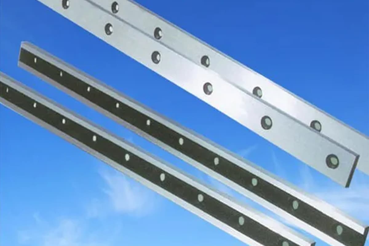
Straight blades are characterized by their simple, linear cutting edge. They perform straight cuts by applying a uniform shearing force along a single axis, ensuring precision and consistency in straight-line cutting.
Key Features:
- Linear Edge: Ensures straight and accurate cuts.
- Uniform Shearing Force: Distributes cutting force evenly across the material.
- Versatility: Suitable for various materials, including metal, plastic, and paper.
Common Applications
Straight blades are widely utilized across numerous industries due to their versatility and dependability. Here are some specific examples illustrating their use:
- Metal Fabrication: In metalworking, straight blades cut sheet metal into uniform sections, used to manufacture components like enclosures, panels, and structural elements. For instance, automotive industries use these blades to cut steel sheets for car body parts.
- Paper Industry: Printing and packaging industries use straight blades to cut paper and cardboard into specific sizes for books, boxes, and other products. An example is the precision cutting of large paper rolls into smaller sheets for notebooks.
- Plastic Processing: Straight blades cut plastic sheets into precise shapes for consumer goods, packaging materials, and industrial components. For example, they are used in the electronics industry to cut plastic casings for devices.
- Textile Industry: These blades cut fabrics into uniform pieces, which are then sewn into garments, upholstery, and other textile products. For instance, in the fashion industry, straight blades are used to cut fabric patterns for clothing.
Advantages and Disadvantages
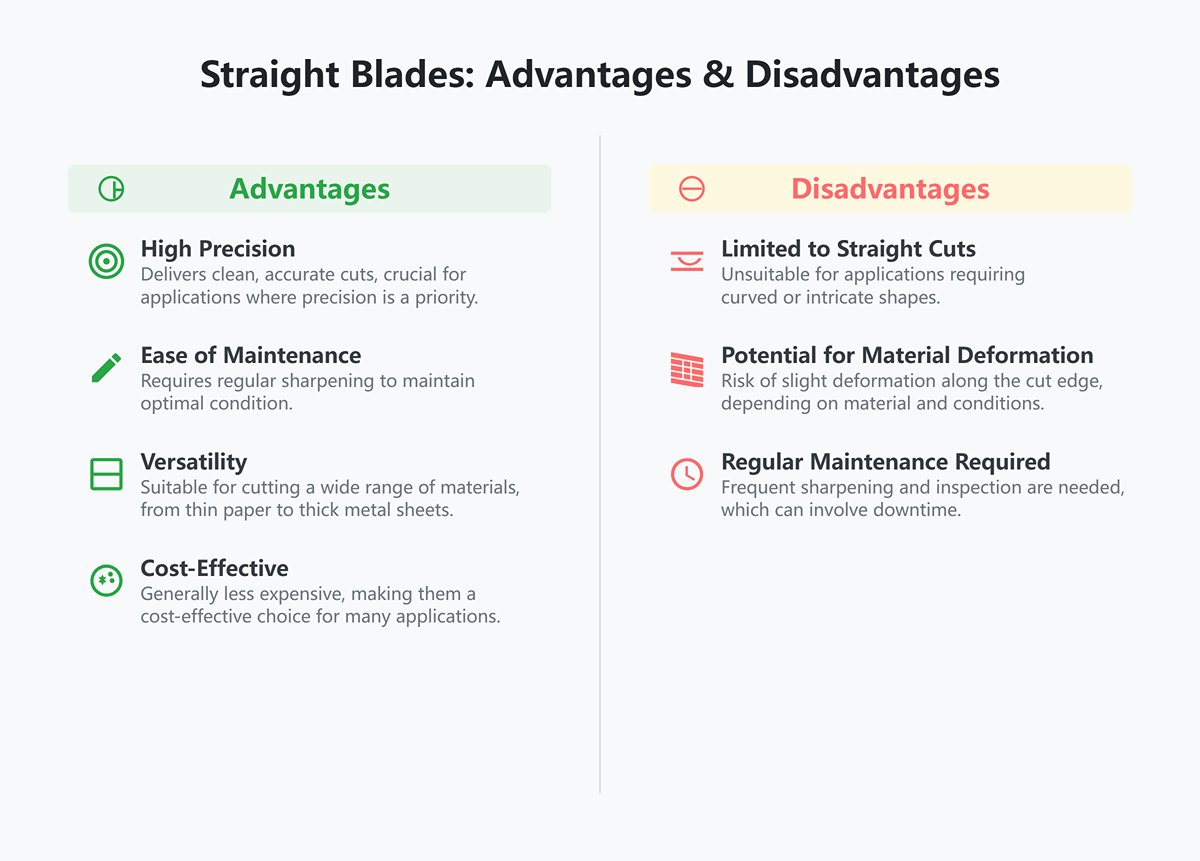
Advantages
- High Precision: Delivers clean, accurate cuts, crucial for applications where precision is a priority.
- Ease of Maintenance: Requires regular sharpening to maintain optimal condition.
- Versatility: Suitable for cutting a wide range of materials, from thin paper to thick metal sheets.
- Cost-Effective: Generally less expensive than more specialized blades, making them a cost-effective choice for many industrial applications.
Disadvantages
- Limited to Straight Cuts: Designed for linear cuts, making them unsuitable for applications requiring curved or intricate shapes.
- Potential for Material Deformation: Depending on the material and cutting conditions, there is a risk of slight deformation along the cut edge.
- Regular Maintenance Required: Frequent sharpening and inspection are needed to maintain cutting efficiency, which can involve downtime.
Rotary Blades
In contrast to the stationary nature of guillotine and shear knives, rotary blades are engineered for continuous, high-speed cutting, especially in environments that require repetitive, rapid cuts. Rotary blades spin as they cut, making them a prime choice for production lines where materials like textiles, paper, or packaging films need to be cut into specific shapes or lengths.
Their rotational motion allows for swift and consistent cuts, making them ideal for high-output applications such as in roll-forming machines and rotary shearing equipment. Rotary blades are especially valued in automated settings, where maximizing productivity is critical.
However, the constant rotational motion means these blades experience frequent contact with materials, leading to a faster rate of wear. Consequently, rotary blades require regular maintenance or replacement, especially in high-demand settings.
While they are not suitable for thicker or highly resistant materials, their efficiency in cutting lighter materials at high speeds is unmatched. Rotary shearing, or cutting via rotation, is well-suited for precision tasks in packaging, textile processing, and paper industries, where the priority is on speed and repetitive accuracy.
Each blade design—guillotine, shear, and rotary—offers unique strengths tailored to specific industrial applications, optimizing performance for different materials and operational needs. These designs not only enable efficient and accurate cuts but also reflect ongoing innovations in blade technology that enhance productivity across diverse industrial contexts.
Comparison of Different Types of Metal Shear Blades
| Blade Type | Primary Use | Cutting Method | Applicable Materials |
| Straight Blades | Precise straight cuts | Direct pressure | Metal, paper, etc. |
| Shear Knives | Multi-purpose metal and non-metal cutting | Shearing | Metal sheets, plastics |
| Guillotine Blades | Heavy material cutting | Vertical downward pressure | Thick metals, plastics |
| Rotary Blades | Continuous rapid cutting | Rotation | Long strip materials |
3. Edge Type-Based Classification
Flat Edge (90°)
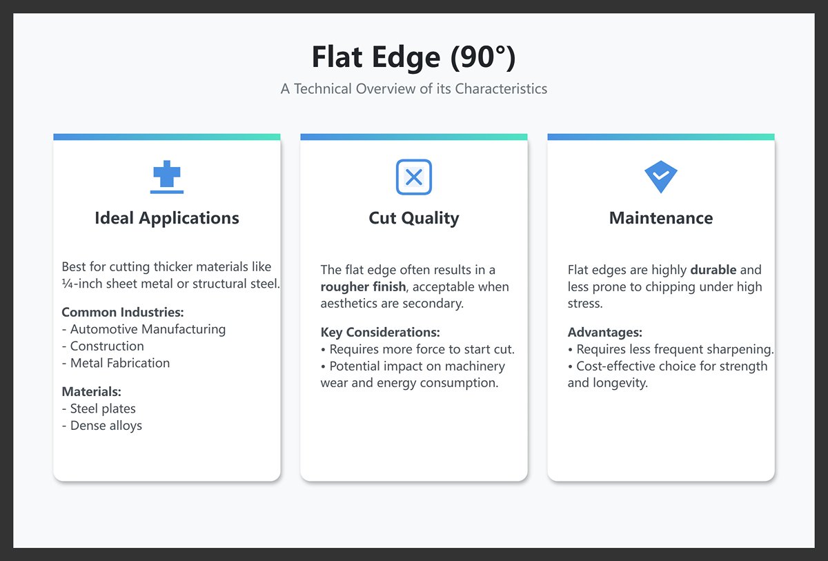
The flat-edge shear blade, or “90° edge,” features a perpendicular cutting angle. This design excels in heavy-duty applications where significant force is needed to shear through thick or hard materials. The 90° angle provides a stable cutting surface that resists deformation under pressure, making it ideal for robust cutting tasks.
- Ideal Applications: Flat-edge blades are best for cutting thicker materials, such as ¼-inch thick sheet metal or structural steel. They are commonly used in automotive manufacturing, construction, and metal fabrication industries, where materials like steel plates and dense alloys are prevalent.
- Cut Quality: The flat edge often results in a rougher finish. While this roughness is acceptable when aesthetic quality is secondary, users should be aware that the 90° edge requires more force to start the cut, potentially impacting machinery wear and energy consumption.
- Maintenance: Flat edges are durable and require less frequent sharpening, as they are less prone to chipping under high stress. This makes them a cost-effective choice for applications prioritizing strength and longevity.
Oblique Edge (82°)
The oblique-edge shear blade, typically angled at 82°, is designed for smooth, precise cuts. This edge type reduces cutting resistance and creates cleaner edges, especially in thinner or softer materials. The oblique design allows for controlled, refined cuts, beneficial in applications where edge quality is crucial.
- Ideal Applications: Oblique-edge blades suit thinner materials requiring fine, burr-free cuts. They are effective for cutting lightweight metals (like aluminum sheets), plastic films, and textiles. Industries such as electronics manufacturing and packaging rely on oblique edges for high-precision cuts that maintain material integrity.
- Cut Quality: The angled edge reduces the force needed to start a cut, resulting in smoother edges with less burr formation (small metal edges left after cutting). This makes the oblique edge ideal for applications demanding high-quality finishes, like final assembly or consumer-facing goods.
- Maintenance: Oblique edges need more frequent maintenance due to their finer angle, which can wear or crack if used on thick or high-tensile materials (materials that resist being pulled apart). Users should match oblique-edge blades with suitable materials, as they may not handle the same stress as flat edges.
4. Designed for Specific Cutting Profiles
Razor Blades
Razor blades are precision tools crafted for cutting thin, lightweight materials with high accuracy, crucial in industries where smooth, burr-free edges are necessary. These ultra-sharp blades excel in applications requiring meticulous detail, such as cutting paper, plastic films, textiles, and delicate foils, where clean cuts ensure material quality and reduce processing times.
- Material Compatibility: Razor blades are highly effective on flexible, thin materials, including polyvinyl chloride (PVC) films, cellophane, and various lightweight plastics. They are ideal for paper-based products, thin fabrics, and films, as their sharp edge prevents burr formation—rough edges that can compromise quality in packaging and textile industries.
- Applications: Razor blades are widely used in packaging to cut plastic wraps and films without damaging the material. In textile production, they allow for fine, fray-free cuts, preserving the fabric’s integrity for high-end garments. Electronics manufacturing also relies on razor blades for trimming delicate components like cable insulation.
- Maintenance: Given their sharpness, razor blades require frequent sharpening or replacement in high-output environments. A well-maintained razor blade preserves its precision, directly impacting production efficiency and product quality.
Scissor Blades
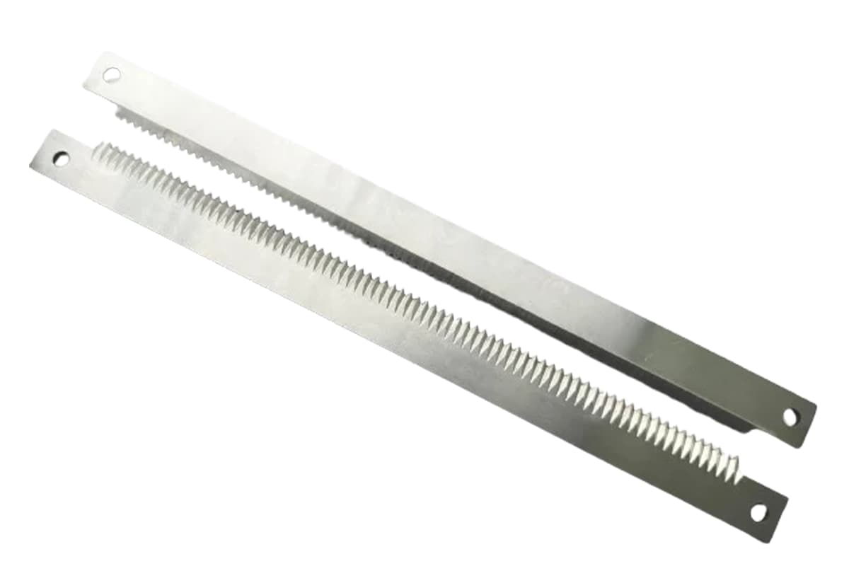
Scissor blades are versatile tools for handheld or automated use, suitable for cutting lightweight, flexible materials with high control. Equipped with serrated or micro-serrated edges, they grip the material firmly, reducing slippage and enhancing precision during manual operations—ideal for intricate designs and complex cuts in various industries.
- Material Compatibility: Scissor blades handle fabrics, paper, and thin plastics effectively, making them indispensable in sectors like tailoring, upholstery, and small-scale fabrication. The serrated edges allow for better grip, especially beneficial for slippery or fibrous materials.
- Applications: Common in tailoring and garment manufacturing, scissor blades are essential for cutting complex fabric patterns without causing fraying. These blades are also useful in packaging and light assembly, providing controlled, manual cuts for thin sheets and wraps, ensuring accuracy where detailed handling is needed.
- Features: The serrated edge gives a firm grip on the material, reducing the risk of slippage and enabling precise cuts. This design is particularly beneficial for high-detail tasks, where maintaining control is crucial.
Notched and Serrated Blades
Notched and serrated blades are designed to provide additional grip and stability for materials that resist smooth cuts. With edges that feature notches or serrations, these blades make effective contact points, ensuring that the material remains steady during cutting. This is particularly advantageous in handling materials prone to slipping or shifting, making these blades ideal for cutting uneven or fibrous materials.
- Material Compatibility: These blades are compatible with materials like rubber, reinforced textiles, leather, and composite materials, excelling where extra stability is required. They are commonly used for materials that are difficult to cut smoothly or tend to shift, such as thick insulation or reinforced sheets.
- Applications: Notched and serrated blades find uses in automotive, leatherworking, and aerospace industries, where they cut resilient materials like rubber insulation, leather, and fiberglass-reinforced plastics. These blades also perform well in environments where materials are layered or reinforced, as the added grip helps maintain cutting accuracy.
- Advantages: The serrated design reduces the force needed to initiate cuts, allowing for smoother, more controlled cuts, especially in high-friction scenarios. This feature minimizes material waste and enhances precision in cutting tough or layered materials.
Tungsten Carbide-Coated Blades
Tungsten carbide-coated blades are engineered for demanding tasks, providing exceptional durability and wear resistance. Known for their hardness, these blades withstand high-stress environments and maintain sharpness over prolonged use, making them indispensable for heavy-duty applications.
- Material Compatibility: Tungsten carbide-coated blades are well-suited for cutting abrasive and hard materials, including fiberglass, ceramics, and hardened metals. The coating reduces friction, enabling smoother cuts even on challenging surfaces while significantly prolonging the blade’s lifespan.
- Applications: These blades are vital in construction, mining, and heavy manufacturing, where materials like concrete, stone, and hard metal alloys require cutting. The coating enhances toughness and wear resistance, making these blades resistant to the wear and tear typical in high-output industrial settings.
- Maintenance: Regular inspections are essential, particularly in high-frequency use, to monitor for edge wear. Blades can be re-coated to restore their cutting efficiency, extending their operational life and maintaining consistency in high-demand settings.
Slotted and Custom Razor Blades
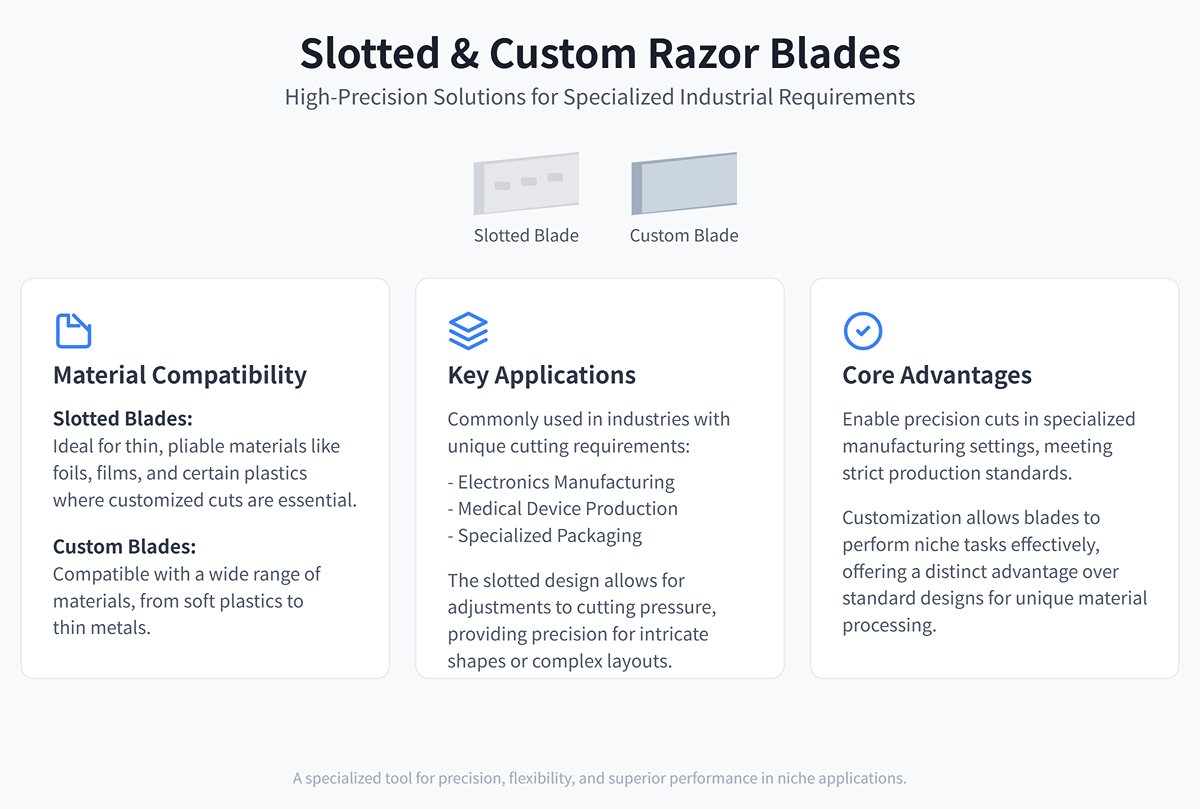
Slotted blades and custom razor blades are tailored for specialized applications, providing high-precision solutions for unique industrial requirements. Slotted blades, featuring small slots or perforations, allow flexible installation in machinery and perform specific cutting actions that align with particular production needs.
- Material Compatibility: Slotted blades are ideal for thin, pliable materials like foils, films, and certain plastics, where customized cuts are essential. Custom razor blades are designed per client specifications and are compatible with a wide range of materials, from soft plastics to thin metals.
- Applications: These blades are commonly used in industries with unique cutting requirements, such as electronics, medical device manufacturing, and specialized packaging. The slotted design allows for adjustments to cutting pressure, providing precision for intricate shapes or complex material layouts.
- Advantages: Slotted and custom blades allow precision cuts in specialized manufacturing settings, meeting strict production standards. Customization enables these blades to perform niche tasks effectively, offering an advantage over standard designs in unique material processing needs.
Ⅲ. Maximizing Value: Blade Lifecycle Management and Optimization
Owning a top-tier blade is only the beginning of winning the battle. To win the entire war, you must establish a full lifecycle management system—from installation and use to maintenance and end-of-life disposal. This isn’t needless bureaucracy; it’s the only way to transform blades from an operating expense into a core asset that continuously generates value. Neglect this stage, and even the most expensive blade will prematurely become scrap.
3.1 Precision Installation: Preventing 90% of Early Failures
The vast majority of early blade failures—whether chipping, abnormal wear, or breakage—stem not from quality issues, but from small oversights during installation. Precision installation is the foundation for achieving the blade’s designed lifespan, requiring operators to act like master watchmakers, following the four principles: clean, flat, even, and accurate.
- Clean & Flat: Creating a ‘Sterile’ Bed for the Blade — Before installing new blades, thoroughly clean the blade seat and the blade itself with a clean cloth and compressed air to remove all metal particles, oil, or dust. Even the tiniest debris can become a deadly stress concentration point under high clamping force—like planting a hidden “landmine” behind the blade—leading to cracks during use. Also, use a precision straightedge and feeler gauge to check that the blade seat is perfectly flat, free from deformation or wear. An uneven base is the quickest way to kill a blade.
- Even: Ending the ‘By Feel’ Approach with a Torque Wrench — Tightening bolts is far from just ‘making them tight.’ Uneven clamping force is the second biggest cause of internal stress imbalance, deformation, and early blade damage.
- Say Goodbye to Brute Force—Use a Torque Wrench: Always use a calibrated torque wrench and follow the torque values specified in the machine’s manual.
- Follow the Golden Tightening Sequence: Tighten bolts in a “center-to-ends, cross-pattern” sequence. First, hand-tighten all bolts; then tighten in three stages (e.g., 50% torque, then 80%, finally 100%). This ensures the blade seats evenly against the mount and pressure is evenly distributed.
- Accurate: Engaging in a ‘Micron-Level Conversation’ with the Blade Using a Feeler Gauge — We already know clearance is the soul of cutting quality, and the art of precision adjustment lies in using a feeler gauge.
- Three-Point Alignment Method: When adjusting, take measurements at least at three positions—both ends of the blade and the center. Manually lower the upper blade holder to the bottom dead center, then insert a feeler gauge of the desired thickness into the gap.
- Aim for a “slight drag” feel: The optimal blade clearance should allow the feeler gauge to slide through smoothly while offering a gentle, consistent resistance—a subtle drag. If the clearance feels too loose or too tight at any point, make fine adjustments until it is perfectly uniform along the entire blade. This is the ultimate expression of craftsmanship.
3.2 Scientific Maintenance and Regrinding: The Art of Maximizing Longevity
If precise installation sets the lower limit for a blade’s lifespan, then scientific maintenance and timely regrinding determine its upper potential.
- When to regrind: Listening to your blade’s “SOS” signals — Waiting until a blade is completely dull and incapable of cutting is the greatest waste. Skilled operators intervene before performance drops off a cliff, guided by the following warning signs:
- Signal One: Increase in burr size — A noticeable rise in the size and number of burrs along the cut edge is the clearest and most reliable indicator of blade dullness.
- Signal Two: Change in cutting noise — When the crisp “click” of cutting turns into a dull, strained “tearing” sound, it means cutting resistance has sharply increased.
- Signal Three: A reflective bright line along the edge — Under good lighting, if you see a distinct white glint along the cutting edge (rounded-off bevel), the blade has shifted from sharp line contact to blunt surface contact and needs immediate regrinding.
- Regrinding standards: Why it must be done by professionals — DIY or non-professional regrinding is a classic case of “saving pennies, losing pounds.” Professional services restore sharpness while preserving the blade’s original geometric precision and material integrity.
- Preserving geometric accuracy: Professionals use high-precision grinding machines to ensure the blade edge remains perfectly parallel to the mounting base and the correct bevel angle is restored. This is essential for maintaining cutting accuracy and extending lifespan in the next cycle.
- Controlling grinding heat: Improper grinding generates excessive heat, which can locally anneal the edge and reduce hardness—dramatically shortening the blade’s next service life.
- The economics of regrinding: How many times can a blade be reworked? — This depends on the material, original thickness, and depth removed each time. High-quality shear blades can generally be reground 3 to 5 times. The decision should be based on a straightforward cost-benefit analysis: as long as the regrinding cost is far lower than buying a new blade, it’s worth doing. Once a blade reaches the manufacturer’s minimum width or thickness specification, it must be scrapped to avoid serious safety risks such as breakage during cutting.

3.3 Common Problems: Blade-Centric Troubleshooting
This quick-reference troubleshooting guide focuses on the blade itself, enabling you to identify and resolve issues swiftly when they arise.
| Problem | Possible Cause | Solution |
|---|---|---|
| Excessive burrs / curling edges | 1. Clearance too large: the blade is tearing rather than shearing the material. 2. Blade dullness: the cutting edge has lost sharpness. | 1. Stop the machine immediately, measure and adjust clearance precisely according to standards (e.g., 5–10% of material thickness). 2. Rotate the blade to a fresh edge or send it for professional regrinding. |
| Blade chipping or premature breakage | 1. Clearance too small: upper and lower blades clashing with a “bite.” 2. Insufficient toughness: blade material cannot withstand the impact of cutting thick or high-strength sheets. 3. Cutting out-of-spec materials: exceeding the blade’s design hardness or thickness limit. | 1. Stop the machine immediately, widen clearance to recommended value. 2. Switch to a tougher blade material such as impact-resistant 6CrW2Si. 3. Strictly follow operating guidelines—no over-spec challenges. |
| Sheet twisting or bowing | 1. Excessive shear angle: especially when cutting narrow strips, too much angle produces torsional force. 2. Insufficient clamping force: sheet not held firmly during cutting, causing movement and deformation. | 1. If equipment allows, reduce shear angle. 2. Check and increase hydraulic clamp pressure to ensure the sheet is firmly fixed at the moment of cut. |
| Crooked cut lines / dimensional drift | 1. Blade not parallel to back gauge reference line. 2. Loose bolt: allowing micro-movement under cutting force. 3. Uneven wear along blade length. | 1. Recalibrate installation to ensure parallelism. 2. Check torque on all locking bolts. 3. Inspect full blade length; if wear is uneven, regrind or replace. |
Ⅳ. Beyond the Price Tag: Strategic Investment and TCO Analysis for Blades
In procurement, the blade’s price tag often becomes the most tempting “center of gravity”—but it can also be the most deceptive strategic trap. Making purchasing decisions based solely on initial price is classic financial short-sightedness; it systematically ignores hidden costs that truly erode profits. This chapter introduces a game-changing way to calculate costs—Total Cost of Ownership (TCO)—to strip away the illusion of price and uncover the genuine value of blades as a strategic investment.
4.1 [Highlight Tool] The Blade Total Cost of Ownership (TCO) Formula
TCO is a financial lens that views a blade’s lifecycle as an integrated value chain, not a one-off purchase. It quantifies every cost from acquisition to disposal, giving you a truly comprehensive basis for decision-making.
TCO = Initial Purchase Price + (Total Downtime Cost + Total Regrinding & Maintenance Costs + Scrap Costs) – Residual Value
- Initial Purchase Price: The most visible cost, but often the smallest portion of TCO.
- Total Downtime Cost: The hidden giant beneath the surface. Calculated as (Planned changeovers + Unplanned changeovers) × Downtime per change × Hourly line value. “Hourly line value” includes lost production output, equipment idle costs, and operator wages.
- Total Regrinding & Maintenance Costs: Includes direct regrinding fees, transport costs, and potential performance loss from improper regrinding.
- Scrap Costs: Waste caused directly by blade performance decline—burrs, deformation, dimensional errors—should be factored into TCO.
- Residual Value: The scrap metal value of the blade at the end of its service life.
The true value of this formula lies in shifting the focus from a static “price” to a dynamic “cost,” compelling us to consider: in order to save 10% on the purchase price, are we actually incurring 30% in downtime costs and a 5% scrap rate?
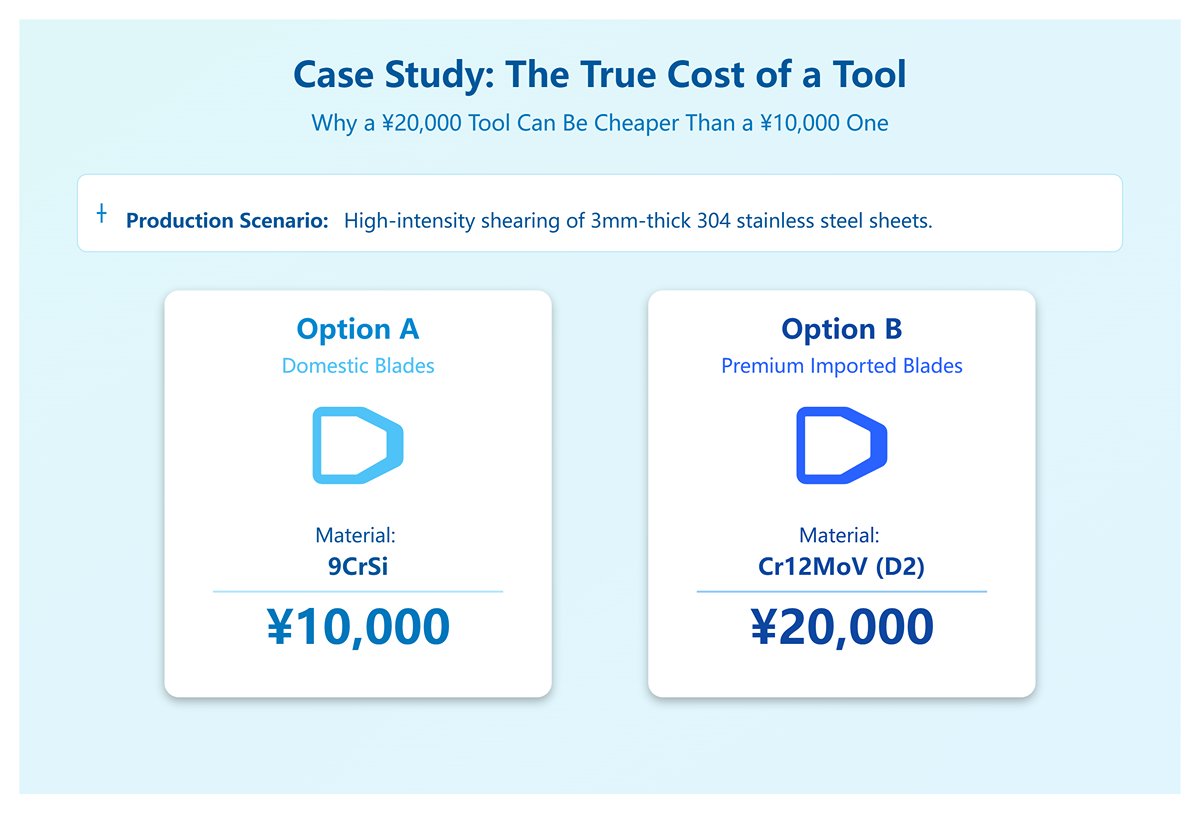
4.2 Case Study: Why a ¥20,000 Tool Can Be Cheaper Than a ¥10,000 One
Let’s step into a real production scenario: a metal products factory needs to continuously shear 3mm-thick 304 stainless steel sheets under high intensity using a hydraulic guillotine. They have two options:
- Option A: Purchase a set of high-quality domestic 9CrSi blades at a price of ¥10,000.
- Option B: Purchase a set of premium imported Cr12MoV (D2) blades at a price of ¥20,000.
First Round: A Simplistic Price-Based Calculation
| Parameter | Tool A (9CrSi) | Tool B (Cr12MoV) | Notes |
|---|---|---|---|
| Initial purchase price | ¥10,000 | ¥20,000 | B is twice the price of A |
| Estimated lifespan (cuts) | 150,000 | 800,000 | Cr12MoV excels in wear resistance |
| Total processing requirement | 800,000 | 800,000 | |
| Unit cutting cost (price only) | ¥0.067/cut | ¥0.025/cut | Even from theoretical lifespan, B leads |
At this point, some managers may already have made their choice. But seasoned experts know—this is only the beginning.
Second Round: A Comprehensive TCO-Based Calculation
Now we factor in hidden costs, assuming the hourly opportunity cost of this production line (lost output + labor) is ¥500.
| TCO Components | Tool A (9CrSi) | Tool B (Cr12MoV) | Calculation Logic |
|---|---|---|---|
| Initial purchase price | ¥10,000 | ¥20,000 | – |
| Replacement count | 5 times (800,000/150,000 – 1) | 0 times (lifespan covers task) | Number of replacements to complete 800,000 cuts |
| Planned downtime cost | 5 × 1.5 hrs × ¥500/hr = ¥3,750 | ¥0 | Each blade change + setup takes 1.5 hrs |
| Unplanned downtime cost | ¥2,000 | ¥0 | Key factor! 9CrSi’s lower toughness means chipping when cutting stainless steel, assumed 4 unexpected stoppages |
| Scrap loss cost | ¥1,600 | ¥0 | Key factor! 9CrSi wears faster later, increasing burrs and causing 0.2% extra scrap rate |
| Total regrinding cost | 5 × ¥400 = ¥2,000 | ¥0 | |
| Final TCO | 10000+3750+2000+1600+2000 = ¥19,350 | ¥20,000 | |
| Actual unit cutting cost | ¥0.0242/cut | ¥0.0250/cut | Very close, A slightly cheaper |
Final Verdict: Introducing the “Production Speed” Variable
It looks like a tie—but we’ve overlooked another crucial advantage of premium blades: performance stability. Cr12MoV blades can maintain a 15% higher cutting speed without compromising quality.
- Tool A total time for 800,000 cuts: (800,000 / N speed) + (5 blade changes × 1.5 hrs) + (4 unexpected stoppages × 0.5 hrs)
- Tool B total time for 800,000 cuts: (800,000 / 1.15N speed)
The calculation shows Tool B saves the factory a significant amount of production time. This extra time can be used to produce more products, generating value that far exceeds the negligible difference in TCO.
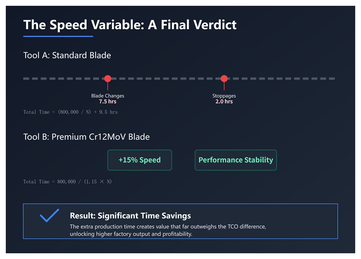
Conclusion: Once we quantify downtime costs, scrap rates, and even production efficiency, the blade with double the initial price not only matches the unit cost of the cheaper one—it also delivers the most valuable asset to the business: time and capacity. That is the essence of strategic investment.
4.3 Supplier Evaluation and Purchasing Guide
Through the lens of TCO, selecting a blade supplier is no longer a simple price comparison—it becomes a comprehensive evaluation of technology, service quality, and strategic alignment.
Request a “Technical ID” and Reject Verbal Promises
Outstanding suppliers are eager to showcase their technical competence. When purchasing, always request and review these three critical documents:
- Material Analysis Report: Confirms that chemical composition meets grade standards—the “genetic” guarantee of performance.
- Heat Treatment Process Report: Details on quenching and tempering temperatures and duration curves—this is the “recipe” that determines the balance between blade hardness and toughness.
- Hardness and Metallographic Test Report: Hardness values (HRC) must be evenly distributed within the optimal range; metallographic images reveal the shape and distribution of carbide particles, offering “microscopic proof” of wear resistance.
Evaluate Depth of Service, Not Just Speed of Response
A strategic supplier should act as a technical partner, not just a salesperson.
- Problem-Solving Ability: When chipping or abnormal wear occurs, do they dispatch technical staff on-site to analyze causes, or simply blame “operator error”?
- Process Optimization Advice: Can they offer professional recommendations on cutting angles and blade clearance based on your operating conditions to maximize blade performance?
- Professional Regrinding Services: Do they provide or recommend expert regrinding that restores blade performance to the fullest, with predictable turnaround times?
Establish Collaborative Inventory, Not Passive Purchasing
For critical blades, building a strategic inventory partnership with your core suppliers can balance spare stock needs against capital tied up. Consider Vendor Managed Inventory (VMI) or consignment models to shift part of the inventory burden and management to professional partners, ensuring spare parts are always available when needed—minimizing the risk of unplanned downtime.
Ⅴ. Conclusion
Selecting the appropriate shear blade is crucial, as it directly influences the efficiency, precision, and sustainability of cutting operations. A thorough understanding of your specific needs, meticulous maintenance, and a commitment to staying updated on the latest technological advancements will ensure optimal performance from your shearing machine and long-term success in various industrial applications.
By adopting new technologies and materials, industries can achieve superior cutting results, extend the lifespan of their blades, and maintain a competitive edge in an ever-evolving market. To explore these advancements in detail, you can download our latest brochures.
In conclusion, the right shear blade is more than just a tool; it is a critical component that significantly impacts the efficiency, quality, and sustainability of cutting operations. Making informed decisions about blade selection, maintenance, and adoption of new technologies will ensure optimal performance and long-term success. If you need assistance in making these informed decisions, feel free to contact us for expert guidance.
IV. FAQs
1. What are the main differences between guillotine blades and shear knives?
| Aspect | Guillotine Blades | Shear Knives (Swing Beam Shears) |
| Cutting Mechanism | Linear motion – upper blade moves straight up and down | Circular arc motion |
| Precision | High precision with controlled blade clearance, providing smooth edges with minimal burrs | Less precision due to larger blade clearance and alignment variations |
| Cutting Angle | Adjustable, reduces material twisting and deformation | Fixed, more prone to material twisting, especially with thin or narrow materials |
| Blade Longevity | Longer lifespan due to four-sided cutting on both blades | Shorter lifespan with two-sided cutting |
| Maintenance | More complex, requires higher maintenance | Simpler structure, easier to maintain |
| Cost | Higher cost due to complexity | Lower cost, making it more cost-effective |
| Application Suitability | Ideal for precision-focused tasks with varying material thicknesses | Suitable for straightforward tasks, particularly with thicker steel plates, where precision is secondary |
2. Are rotary blades suitable for all types of hydraulic shearing machines?
Rotary blades are not universally suitable for all hydraulic shearing machines. They are primarily designed for continuous cutting in specific applications, such as roll-forming machines and rotary shearing equipment, where they cut materials into defined shapes and lengths.
Most hydraulic shearing machines, like guillotine shears and power shears, require a different cutting action, typically using fixed upper and lower blades rather than rotary ones.
Additionally, the material type and thickness are crucial considerations: rotary blades can manage continuous cuts on certain materials, but thicker or harder metals often require the strength and precision of fixed blades in hydraulic shears. Consequently, rotary blades are limited to specific machine designs and applications, making them unsuitable for general-purpose plate shearing across all hydraulic machines.