Press Brake Metal Bending Explained: Geometry, Tonnage, Springback & CNC Precision

Factory-sale Equipment
We have over 20 years in manufacturing. 
Press Brake
Laser Cutting Machine
Panel Bender
Hydraulic Shear
Get FREE Quote
Publish Date: April 7, 2026

You press the pedal. The ram descends with 100 tons of force. The 10-gauge cold-rolled steel groans, bottoms out in the V-die, and you release the pedal. You remove the part expecting a precise 90-degree bracket. Instead, it measures 93 degrees, with a hairline fracture running along the outside radius.

Your first reaction is to place it back in the machine, adjust the stroke, and press the pedal harder. But sheet metal is not clay. It does not simply assume the shape of whatever force you drive it into.

If you want a clearer mental model of what is actually happening between the punch, die, and material during this moment, this technical breakdown of how a press brake works explains the mechanics step by step—from force application to elastic recovery. Manufacturers like ADH Machine Tool, whose CNC bending systems are developed through dedicated R&D and testing across press brake and automation platforms, design their equipment around these geometric and material principles rather than raw tonnage alone.

Bending metal is more like a negotiation than a contest of strength. If you attempt to overpower the material, you will likely scrap a significant amount of costly stock before the day is half over.

Related: Mastering CNC Press Brake Forming

The Brute-Force Trap: Why "Pressing Harder" Leads to a Ruined Part

When you stand before a machine capable of delivering 200,000 pounds of pressure per square foot, it is easy to treat every issue as something to be hammered into place. You may think of the punch as an anvil and the die as a mold. However, if you depend on tonnage alone to determine your bend angle, you are working against the fundamental physics of metallurgy.

What actually occurs along the metal's neutral axis during a bend?

Pick up a thick rubber eraser and bend it in half. Observe the edges. The outer curve stretches, pulling the rubber tight. The inner curve compresses and wrinkles. Yet in the exact center of the eraser, a thin layer remains the same length.

This is the neutral axis. Sheet metal behaves in the same way.

As the punch forces the material into the die, the outer radius of the steel is placed in tension and stretches. The inner radius is placed in compression and compresses. The neutral axis is the only region of the sheet that does not change length. When the ram is released, the compressed inner fibers push outward, and the stretched outer fibers pull back. This is springback. In a standard air bend, you cannot eliminate springback simply by applying more force. So how do you manage a material that actively tries to reverse your work?

One action, six variables: Why seemingly identical sheets produce different results

Take two sheets of 0.120" aluminum that appear identical but come from different pallets. Bend them using the same tooling, the same ram depth, and the same tonnage. One reaches 90 degrees. The other stops at 92 degrees.

Why? Because metal is rolled, not printed.

Grain direction from the steel mill affects how the material responds to tension. Yield strength differs from batch to batch. Thickness carries a manufacturing tolerance—that "0.120 inch" sheet may actually read 0.118" or 0.124" on your calipers. Then factor in the punch tip radius, the die opening width, and the friction coefficients of your tooling. Six variables are already shifting under your hands before the machine is even powered on. If you treat bending as a single action—simply "pressing"—you overlook the matrix of conditions that truly form the part. If identical sheets respond differently to the exact same pressure, how can we realistically hold a tolerance of half a degree?

The Metal Bending

The shift from anvil to mathematical mold: Why precision, not pressure, determines success

Think of the press brake not as a hammer, but as a calculator powered by hydraulic cylinders.

We are not forcing the metal into shape. We are calculating exactly how much space it needs to attempt to spring back, so it settles precisely where we intend. We over-bend by a calculated number of degrees, knowing the neutral axis will pull the flanges back once the pressure is released. We widen the die opening to adjust leverage, rather than pushing the machine to maximum tonnage. We stop viewing the punch as a stamp that determines the final angle and start seeing it as a fulcrum.

The moment you stop trying to crush the metal and begin negotiating with its geometry, you stop being just a machine operator. You become a fabricator. But if the punch does not dictate the final angle, what actually does?

The Illusion of the 90-Degree Punch: Why You Should Probably Be Air Bending

Walk into any fab shop, find the newest person on the floor, and ask him to make a 90-degree bracket out of 11-gauge 304 stainless. He will go straight to the tooling rack, select a punch marked 90 degrees and a die cut to 90 degrees. He will bottom out the ram, remove the part, and stare in complete confusion at a bracket measuring 93 degrees.

He has fallen for the illusion of the 90-degree punch. In modern fabrication, the angle machined into your tooling rarely matches the angle you want in the finished part. Tooling geometry is merely a boundary. The real bending occurs in the empty space between the punch and the die. If the punch is not stamping the angle into the metal, how do we make the material conform to our dimensions?

Coining vs. Bottoming: When does forcing the metal justify the risk to your tooling?

Coining requires five to eight times the tonnage of air bending. If you attempt to coin a 10-foot piece of 1/4-inch mild steel, you are not merely bending it. You are forging it. You are thinning the material at the point of impact to permanently erase its molecular memory.

Coining forces the metal to exactly replicate the punch and die. It eliminates springback entirely because you are physically crushing the neutral axis until it yields. It provides absolute, foolproof repeatability. But that predictability comes at a significant cost. Applying that much force damages press brake beds, wears down expensive tooling, and drives hydraulic systems toward their limits. Bottoming offers a partial compromise—pressing the material into the die just enough to set the angle without thinning it—but it still requires substantial tonnage. If brute-forcing the angle is so damaging to our equipment, why do some high-end aerospace and medical shops continue to rely on it?

They use it when a half-degree of variation would scrap a million-dollar assembly. But for 95 percent of fabrication work, destroying your tooling to guarantee an angle is a futile effort. If we remove brute force from the equation, how do we achieve the same precision without damaging the machine?

The air bending advantage: How reduced physical contact actually delivers greater control

What Is Press Brake Crowning

In an air bend, the sheet metal contacts the tooling at only three points: the very tip of the punch and the two upper shoulders of the V-die. The metal never touches the bottom of the V.

This is where the press brake stops acting as a crusher and becomes a mathematical wedge. Because the material is suspended across the die opening, the final angle is determined entirely by how far the punch drives the metal into that empty space. Lower the ram a quarter inch, and you get a 135-degree obtuse angle. Lower it another eighth of an inch, and you reach 90 degrees. You use the exact same punch and die to produce an infinite range of angles. You gain full adjustability, significantly lower tonnage requirements, and extended tooling life. But this flexibility introduces a new variable. If the metal is suspended in the die, what prevents it from springing back out of tolerance as soon as the punch retracts?

The springback tax: Why the machine's stroke angle will never equal your final part

Bend a piece of 5052 aluminum to exactly 90 degrees under pressure, and it will relax to 91.5 degrees once you release the pedal. Bend a piece of 304 stainless to 90 degrees, and it will spring back to 93 or 94 degrees.

That elastic recovery is the springback tax. Because air bending depends on empty space rather than physical stamping, you must account for this tax on every bend. To achieve a 90-degree part in stainless, the machine's stroke must drive the metal deep enough to reach 86 degrees. You intentionally overbend the material to a tighter angle, knowing the neutral axis will pull the flanges back open by exactly four degrees once the pressure is released. The stroke angle is only a temporary waypoint. The relaxed state is the true destination. Modern CNC brakes use optical sensors to measure and adjust this in real time, but the underlying physics remain unchanged. You are not forcing the metal to hold an angle. You are calculating its exact path of recovery and capturing it at your target dimension. But if punch depth determines the angle, what determines the inside radius of that curve?

Tooling Is a Decision, Not an Accessory: Selecting Your Punch and Die

Take a piece of 16-gauge mild steel and form it with a 1/32-inch radius punch over a 1/2-inch V-die. The inside radius of the resulting bend will not be 1/32 inch. It will be approximately 0.080 inches. Replace that punch with a sharper 1/64-inch tip, cycle the ram again, and the metal will still form a 0.080-inch radius. In air bending, the punch tip does not control the inside radius. The die opening does.

The metal spans the gap between the two shoulders of the V-die, and as the punch descends, the material forms its own natural curve determined entirely by the width of that gap. A wider die opening produces a larger inside radius; a narrower opening produces a tighter one. Your flat pattern calculations depend entirely on this resulting inside radius to determine bend deductions and flat lengths. If you guess the die opening, your flat pattern is incorrect before the laser even cuts the blank. But if the die opening governs the radius, how do we know which width to select from the rack?

The "Rule of 8" for V-die selection: Absolute law or merely a beginner's starting point?

Walk up to any standard tooling rack, measure a V-die opening, and divide it by eight. The result is the material thickness it was intended for. The "Rule of 8" states that the V-die width should be exactly eight times the material thickness. For 1/8-inch steel, you would select a 1-inch die.

This 8-to-1 ratio delivers optimal mechanical advantage, keeping tonnage demands manageable while reducing the risk of metal fracture. However, treating this rule as absolute will eventually damage your parts. Try bending 1/4-inch Hardox wear plate with a standard 2-inch die. The material is too rigid to flow smoothly into such a narrow opening, and the outer surface of the bend will crack like dry soil. Harder materials and thicker plates require a 10-to-1 or even 12-to-1 ratio to reduce tensile strain on the outer fibers. Conversely, applying a 12-to-1 ratio to thin mild steel allows the material to drift within the wide opening, producing highly inconsistent angles. If the die opening determines the radius and the material determines the die opening, where does the punch shape come into play?

The Rule of 8 in V-Die Bending

Punch profile geometry: When does a standard straight punch become inadequate, requiring a gooseneck?

Imagine a standard straight punch descending into a sheet of metal to form a simple U-channel. The first 90-degree bend is completed without issue. You flip the part to make the second bend, press the pedal, and see the first flange collide directly with the flat face of the straight punch before the ram finishes its stroke.

Straight punches are inexpensive and rigid, but they do not account for the metal wrapping around them. To clear existing flanges, a gooseneck punch is required. A gooseneck features a pronounced, sweeping undercut machined into its face, creating a physical void for the previously bent metal to occupy while the tip completes the new bend. Clearance is not their only function. When forming short flanges—anything less than 1.5 times the die width—a straight punch causes uneven material flow, pulling the metal asymmetrically and leading to edge wrinkling. The relieved geometry of a gooseneck allows the short flange to pivot upward without binding against the tool face. If punch geometry prevents collisions and die width defines the radius, how can these variables be fixed into a repeatable system?

Reading a tooling chart without guessing: Matching die opening to inside radius and material thickness

Examine the tooling chart mounted on the side of a 100-ton press brake. It represents pure geometry in matrix form. Locate the material thickness on the Y-axis, move across to the selected V-die opening on the X-axis, and the intersecting cell provides two essential values: the resulting inside radius and the required tonnage per foot.

You do not estimate the radius for your CAD software; you take it directly from this chart. However, tooling charts assume ideal three-point bending, where the metal maintains symmetrical contact with the punch tip and die shoulders. If the punch and die are misaligned by even a few thousandths of an inch, the metal shifts, the radius becomes distorted, and the chart’s calculations no longer hold. Modern CNC press brakes eliminate manual charts, using real-time angle sensors to measure tool deflection and springback during the cycle and adjust the stroke accordingly. Advanced systems such as the CNC press brakes from ADH Machine Tool integrate fully CNC-controlled bending with automation-ready architectures, bridging the gap between geometric theory and repeatable production accuracy. Even so, the most advanced sensor cannot correct a physical mismatch between material and machine. Software can modify plunge depth, but it cannot change die width. If tooling geometry defines the physical limits of the bend, how much mechanical force is required to drive the material to that limit?

Stop Guessing Tonnage: The Force Calculation That Protects Your Machine

Your die width is set. Your flat pattern is mathematically correct. Yet geometry alone will not bend the metal—it only defines the physical constraints of the bend. Forcing a 10-foot sheet of 1/4-inch mild steel into a standard V-die requires approximately 150 tons of mechanical force. Miscalculate that requirement by just 10 percent, and you have directed the equivalent weight of three full-size pickup trucks into a hardened steel tool.

Beginners see a 200-ton press brake and assume it can bend anything that fits between the jaws. This is how machines become permanently sprung and tooling gets ruined. The press brake does not recognize the material placed in the die. It only registers how far you instruct the ram to travel, and it will apply its full rated capacity to reach that programmed depth. If the metal’s resistance exceeds the structural limits of your punch and die before the ram completes its stroke, the machine will not stop. It will continue driving the punch into the die, permanently embedding one into the other. Safeguarding your equipment requires calculating the precise force needed to yield the material before you ever press the pedal.

Breaking down the tonnage formula: Which hidden variable trips up beginners the most?

Standard U.S. tonnage charts are based on a specific benchmark: AISI 1035 cold-rolled steel with a tensile strength of 60,000 PSI. The baseline formula for air bending this material is simple: tonnage equals 575 multiplied by the material thickness squared, multiplied by the bend length, divided by the die opening.

However, operators rarely bend perfectly standard steel, and this is where the calculations become risky. The hidden variable that confuses beginners is the multiplier associated with the bending method. The baseline formula assumes air bending, which uses a method factor of 1.0. If you choose to bottom-bend the same piece of steel to achieve a sharper radius, you must multiply the required tonnage by 5.0. If you attempt to coin it, the multiplier increases to 10.0. An operator who consults an air-bending chart for a bottom-bending operation will underestimate the required force by 500 percent. They will program a 30-ton bend, command the machine to drive to the bottom of the die, and then watch as the brake attempts to apply 150 tons of force into tooling rated for 50.

PRESS BRAKE TONNAGE CALCULATION

The exponential cost of thickness: Why doubling material thickness more than doubles the required force

Take a 1-inch-long piece of 1/8-inch mild steel and air bend it over a 1-inch V-die. It requires about 0.9 tons of force. Now place a piece of 1/4-inch steel into that same 1-inch die. You doubled the thickness, so you might expect the force to increase to 1.8 tons. It does not. The required force rises to nearly 3.6 tons.

Given that ADH Machine Tool's product portfolio is 100% CNC-based and covers high-end scenarios in laser cutting, bending, grooving, shearing, for teams evaluating practical options here, Tandem Press Brake is a relevant next step.

Examine the formula carefully: thickness is squared ($t^2$). Bending resistance increases exponentially because you are not merely pushing more metal into the opening. You are simultaneously stretching a thicker outer fiber and compressing a thicker inner fiber, doing so over a relatively tighter span. When you double the material thickness without enlarging the die opening, mechanical leverage drops sharply. This is why the "Rule of 8" for die selection exists. If you double the material thickness to 1/4 inch, you must also double the die opening to 2 inches to preserve the same 8-to-1 mechanical advantage. By widening the die, you increase the denominator in the formula, reducing the required tonnage back to a linear relationship. Ignore the exponential effect of thickness, and the metal will resist more forcefully than your machine can deliver.

Concentrated load limits: What happens when you force high tonnage into a narrow V-die?

A European-style gooseneck punch is typically marked with a maximum load rating—often around 15 tons per foot (or approximately 44 kN/m, depending on the manufacturer’s unit convention). Now consider bending a heavy, 6-inch-wide steel bracket that requires 30 tons of force to yield.

Your 100-ton press brake easily has the overall capacity for a 30-ton job. But consider the distribution. You are applying 30 tons of force over just 6 inches of tooling. That equals a concentrated load of 60 tons per foot. You have exceeded the punch’s structural limit by 400 percent. When tooling is overloaded to this extent, hardened steel does not bend or deform—it shatters. A V-die that splits down the center under extreme concentrated load can launch shrapnel across the shop floor at bullet-like speed. This is the central pitfall in tonnage calculation: confirming that the machine has sufficient total power while failing to verify whether the specific inches of tooling in contact can withstand that concentration of force. You must calculate both the machine’s total tonnage and the tooling’s tonnage per inch.

Where Perfect Calculations Fail: Grain Direction and Material Edge Cases

You ran the calculations. You chose a heavy-duty V-die wide enough to keep tonnage per inch out of the danger zone, and a punch thick enough to handle the concentrated load without shattering. The machine is safe. The tooling is safe. You press the pedal, the ram descends, and your 6061-T6 aluminum snaps in half like a dry saltine.

Bending metal is a hostage negotiation, not a wrestling match.

You do not force the material into submission. You determine precisely how much room it needs to attempt to spring back so it settles exactly where you intend. Mathematical formulas, however, assume a perfect and uniform world. On the shop floor, metal is grown, rolled, and stressed. If your tooling selection accounts only for machine safety and ignores the sheet’s metallurgy, the part will still end up as scrap.

Bending with the grain vs. against it: Which orientation leads to immediate cracking?

Sheet metal has a grain, much like wood. When the mill rolls the sheet flat, the alloy’s crystalline structure elongates into long, microscopic fibers running parallel to the rolling direction. This directional structure affects how the material responds to tension.

If you align your punch parallel to those fibers—bending with the grain—you are effectively driving a wedge between them. The metal does not stretch; it splits. To avoid this, you must bend against or across the grain. This forces the microscopic fibers to wrap around the punch, using their longitudinal strength to withstand the tensile stress of the bend. If your nesting software prioritized material yield over grain direction and you attempt a tight radius bend parallel to the grain on a stiff alloy, no amount of accurate tonnage calculation will prevent failure. The part will fail immediately.

Minimum bend radius: The material’s physical limit you cannot negotiate

This brings us to the material’s inherent physical limit. Every alloy has a minimum bend radius—the tightest possible inside bend before the outer fibers tear.

You may have determined that an 8-to-1 die ratio provides safe tonnage for your tooling. But if that die opening produces an inside radius of 0.062 inches, and your specific aluminum grade requires a minimum bend radius of 0.125 inches, the calculation is misleading. The tool will survive, but the part will crack. The minimum bend radius is not negotiable. If the material requires a larger radius to withstand the stretch, you must increase the punch tip size and widen the V-die accordingly. The material determines the tooling, and the tooling determines the tonnage.

Stainless, aluminum, and high-strength steel: Same formula, vastly different elastic recovery

Even after you account for the grain direction and maintain the minimum radius, you still have to confront springback. Every material attempts to return to a flat state once the ram releases. Mild steel is very predictable. You overbend it by a degree or two, and it relaxes precisely to 90 degrees.

Replace that mild steel with 304 stainless, and you are suddenly facing a significant springback penalty. Stainless steel work-hardens during bending. The more you force it, the more resistance it generates, often requiring a V-die opening 8 to 10 times the material thickness to accommodate the strain. Aluminum may demand a completely different overbend angle depending on its temper, and high-strength steels such as AR400 can spring back so aggressively that you may need to overbend by as much as 15 degrees to achieve a final 90. The tonnage calculation formula appears identical on paper, but elastic recovery varies dramatically. You must modify your punch angle and die width to provide these high-strength materials with sufficient room to overbend, altering the geometry of the entire setup.

Given that ADH Machine Tool invests more than 8% of annual sales revenue in research and development. ADH operates R&D capabilities across press brakes, if the next step is to speak with the team directly, contact us fits naturally here.

The Pre-Bend Setup Checklist That Eliminates 90% of First-Part Scrap

The calculations indicated which tooling would withstand the material’s springback and grain structure. However, paper does not bend. Once you install that tooling in the press brake, you introduce a significant hydraulic variable. The setup checklist is not about rechecking your math; it is about identifying precisely where the physical machine deviates from your calculations.

Aligning the backgauge: Where do most dimensional errors actually originate?

You slide a 10-foot sheet of 14-gauge cold-rolled steel against the backgauge fingers, press the pedal, and inspect the part. The ends measure a perfect 90 degrees. The exact center measures 92 degrees.

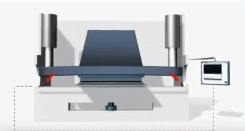
A novice immediately reaches for a wrench to adjust the backgauge, assuming the part slipped. The backgauge is not at fault. The error originates in the steel frame of the press brake itself. When the hydraulic cylinders apply force to the ends of the upper beam, the resistance from the sheet metal pushes back at the center. This causes the upper beam to bow slightly upward in the middle by a few thousandths of an inch—a phenomenon known as ram deflection. If the punch does not penetrate as deeply at the center, the bend angle opens.

When the angle opens, the horizontal projection of the flange changes.

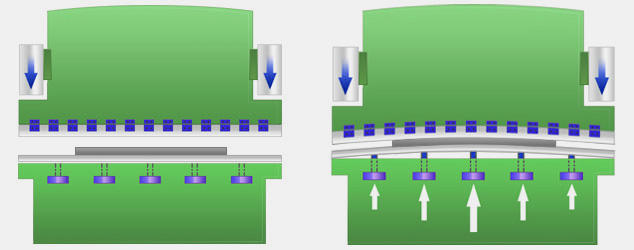
You will spend hours chasing dimensional discrepancies with your calipers if you do not recognize that the machine is bowing under load. You must set the crowning—the mechanical wedge system in the lower bed that bows the die upward to match the ram’s deflection—before relying on any backgauge dimension. Once the bed and ram are perfectly parallel under load, you can trust what your calipers indicate.

The first test bend: Should you measure the angle or the flange length first?

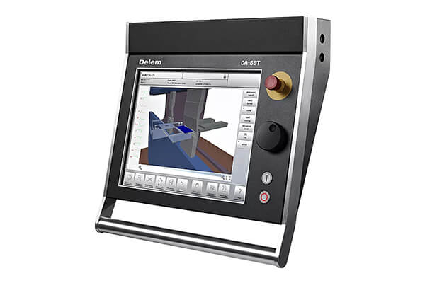
CNC Control System

You are targeting a 2.000-inch flange at a 90-degree angle. Your first test piece comes out, and the calipers show a flange length of 2.025 inches.

The instinct is to go to the controller and move the backgauge forward by twenty-five thousandths. Do not adjust the backgauge. Instead, pick up your protractor. In air bending, the sheet rests on the two shoulders of the V-die while the punch descends into the open space. Because the material is angled upward during the stroke, any change in the bend angle directly affects where the material’s edge sits in three-dimensional space. If the angle is 88 degrees instead of 90 due to unexpected springback, the flange will measure longer.

The length is an illusion caused by the angle.

If you adjust the backgauge to correct the length, you are embedding an error in the CNC program. When you later correct the angle, your flange will suddenly measure short. Always measure and correct the angle first. The angle is the basis of the geometry; the flange length is merely a byproduct.

Dialing in the compensation: How to adjust your ram depth based on the test bend's physical feedback

Your protractor shows 91.5 degrees with a 90-degree target. You need to eliminate a 1.5-degree error.

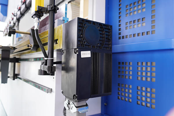
Modern CNC press brakes often include optical sensors that measure the angle in real time and automatically drive the ram deeper until the target is reached. However, if you depend entirely on a laser, you will not understand the mechanical link between depth and degree. In a standard V-die, changing the bend angle by one degree requires adjusting the ram depth by about 0.004 inches. This is your conversion factor. To correct a 1.5-degree error, you do not simply lower the ram and guess. You program an exact 0.006-inch negative depth correction.

Given that ADH Machine Tool's product portfolio is 100% CNC-based and covers high-end scenarios in laser cutting, bending, grooving, shearing, for teams evaluating practical options here, Electric Press Brake is a relevant next step.

You are using the first part as intended: as a diagnostic tool to quantify the material’s unaccounted-for springback. You measure the deviation, convert the degrees into thousandths of an inch, and enter the precise depth correction. You confirm the angle is exact, and only then do you use your calipers on the flange to check the backgauge. This is how you stop fighting the machine and begin controlling the system.

If you want structured reference material to support this level of control—covering CNC-based bending systems, frame rigidity design, and production-level consistency—you can download the detailed technical brochures from ADH Machine Tool to review machine specifications, configuration options, and quality control standards that align with this data-driven approach to press brake setup.

The Shift That Changes Everything: You’re Controlling Elastic Recovery, Not Forcing Metal

You just spent twenty minutes dialing in the perfect first part. The crowning is set, the angle is exact, and the flange length measures precisely 2.000 inches. You secure the tooling, pull the next blank from the pallet, and run the machine. The second part measures 91 degrees.

Welcome to production.

That perfect first part was misleading. Sheet metal is not a uniform synthetic material; it is a rolled product with internal stresses. Mill tolerance on a sheet of 14-gauge steel allows thickness variations of up to 0.007 inches from batch to batch, or even from the sheet’s edge to its center. When thickness changes, the inner radius changes. When the radius changes, elastic recovery changes. If you expect a fixed machine setup to produce identical results across a 500-part run, you will scrap half the pallet.

Mechanical Crowning

What would you do differently if springback were your starting assumption rather than an afterthought?

The novice sees springback as a nuisance that disrupts a good calculation. The fabricator sees springback as the only calculation that matters.

If you begin with the understanding that the material will always attempt to return to its original flat condition, your entire approach to the press brake shifts. You stop viewing the punch as a hammer and start seeing the V-die as a controlled containment zone. You recognize that coining—applying extreme tonnage to compress the metal so forcefully that its elastic memory is effectively erased—is a brute-force method suited to prototyping that damages tooling, not a sustainable production practice. In air bending, you are not forcing the metal into a form. You are calculating the precise amount of over-travel required so that it relaxes into the intended dimension.

Modern press brakes attempt to perform this analysis for you. Real-time optical sensors can measure the bend angle during the cycle and automatically drive the ram deeper to compensate for material variation as it occurs.

However, a laser cannot explain why the angle is incorrect.

If you rely blindly on automation to chase a changing angle, you will eventually damage the machine. The sensor may register a shallow bend and command the ram to descend further, unaware that the true problem is a mechanical interference where the part’s return flange is striking the punch body. Automation addresses the symptom. You must control the system.

From confused operator to confident fabricator: A simple diagnostic framework for bad bends

When a part goes out of tolerance during a run, the operator guesses. The fabricator diagnoses. With the mechanical understanding you now have, you can troubleshoot any bending failure by isolating variables in a strict sequence.

First, examine the spatial constraints. Before adjusting any hydraulic settings, inspect the physical clearances. Are you truly dealing with springback, or is the part physically binding against the tooling? Complex forms such as boxes can create deadlocks in which the bend sequence causes interference. If the flange is striking the die block, no increase in tonnage or ram depth will correct the angle.

Second, evaluate the structure. If the angle is correct at the ends but shallow in the center, the material properties did not suddenly change. Your machine is deflecting. Punch penetration is being lost to ram bowing. Adjust the crowning to counteract the deflection before modifying the CNC depth compensation.

Third, interpret the material. If the clearances are correct and the crowning is level, yet the angle opens up along the entire bend length, the material itself has changed. You may be working with a harder batch of steel or a sheet rolled toward the upper limit of thickness tolerance. Elastic recovery has increased. Do not react impulsively. Measure the deviation, calculate the required thousandths-of-an-inch depth adjustment for that specific V-die, and modify the ram to allow additional overbend.

Bending metal is a negotiation, not a contest of force.

You cannot force the material into submission. The moment you stop attempting to overpower the steel and begin mathematically anticipating its elastic recovery is the moment you gain control of the machine. You provide the metal with precisely enough overbend, knowing that its natural recovery will bring it back within exact tolerance. You are no longer simply pressing a pedal. You are a fabricator.

infographic

Download the Infographic With High Resolution

Looking for Machines?

If you're looking for sheet metal fabrication machines, then you've come to the right place!

Our Customers

The following big brands are using our machines.
Contact Us
Not sure which machine is right for your sheet metal product? Let our knowledgeable sales team guide you in selecting the most suitable solution for your needs.
Ask An Expert
Privacy PolicyTerms
Copyright © 2026
linkedin facebook pinterest youtube rss twitter instagram facebook-blank rss-blank linkedin-blank pinterest youtube twitter instagram