Laser Cutting Machine Basics: Why Power and Speed Should Be Your Final Adjustments

Factory-sale Equipment
We have over 20 years in manufacturing. 
Press Brake
Laser Cutting Machine
Panel Bender
Hydraulic Shear
Get FREE Quote
Publish Date: May 9, 2026

Many users expect a laser cutter to function with the same effortless setup as a typical office printer. Achieving professional-level laser cuts, however, is not a matter of software settings—it is a matter of physics. You must first understand the unseen dynamics of focal distance and air pressure before altering the speed or power controls.

Related: Mastering Laser Cutting Machine Workflow

The "Just Turn It On" Mistake: Why Treating a Laser Like a Printer Ruins Materials

I’ve seen many capable individuals unbox their laser cutter, connect the exhaust, and assume setup is complete. But if you treat the device like an inkjet printer—pressing “send” and waiting—you won’t end up with a clean cut. Instead, you risk starting a small but costly burn.

The beam doesn’t cut—it vaporizes, and that changes everything

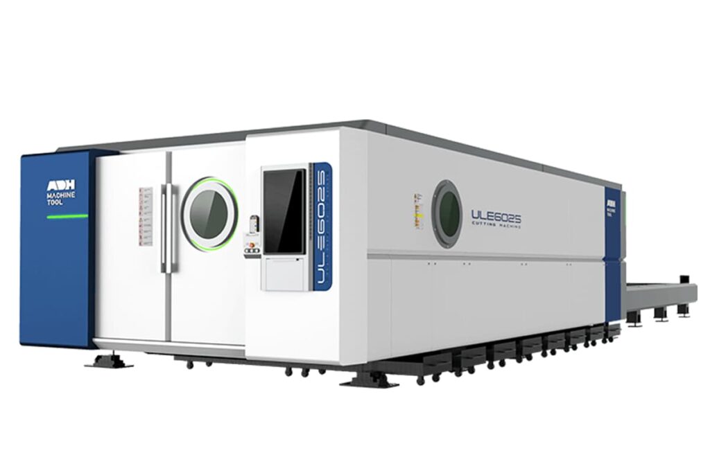
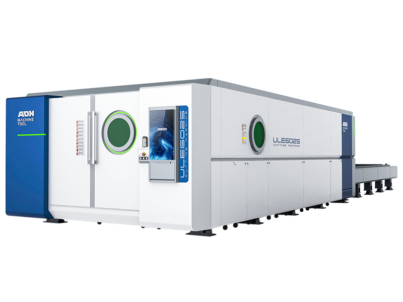
A table saw removes material by tearing it away with steel teeth, while a laser removes it by vaporizing it completely. For operations where precision vaporization defines the cut quality, professional systems such as the ADH Machine Tool Single Table Fiber Laser Cutting Machine ensure consistent accuracy and efficient energy use across varied materials.

When a diode laser strikes wood, it concentrates intense thermal energy on a microscopic point until the solid turns to gas and carbon almost instantly. If the vaporization happens too slowly, heat spreads sideways into surrounding areas, causing scorch marks.

Think of the beam less like a pencil and more like an hourglass made of fire. Your goal is to control exactly where that narrowest point occurs. If the focal point isn’t placed precisely inside the material, you’re not cutting efficiently—you’re simply dragging a heated, unfocused light across combustible wood.

Why newcomers tend to pursue higher wattage instead of better alignment

Place a meter under a typical 50-watt laser, and testing often reveals a consistent limit: its true optical output tops out around 36 watts when set to 80% power in software. Pushing it to 99% doesn’t yield a deeper cut—the output simply levels off. For operations that demand higher throughput without relying on wattage increases, ADH Machine Tool’s precision-driven engineering offers a smarter path. Their Double Table Fiber Laser Cutting Machine keeps output consistent while automating material changeover, helping maintain peak efficiency under identical power conditions.

Still, when a cut fails to go through, beginners often respond by increasing power or investing in a larger tube, assuming the problem lies in insufficient strength. In most cases, though, the issue is poor focus. A sharply aligned 10-watt beam can slice through material more effectively than a misaligned 50-watt beam that merely scorches its surface.

Pursuing higher wattage is an unnecessary expense. Proper mirror alignment, lens cleaning, and precisely set focal distance according to manufacturer specifications cost nothing yet provide the cutting performance you assumed more power was needed to achieve.

Speed vs. Power: Why these controls simply reflect your physical configuration

laser cutting machine

Check any manufacturer’s speed and power chart. It will assert that 1/10" plywood should be cut at 15.7 inches per minute using a 10-watt diode. Yet the small print always repeats the same reminder: “Test on scrap first.”

If speed and power were fixed digital constants, a chart would suffice. Those charts assume your lens is clean, your focal distance is precisely calibrated, and your air assist is forcefully clearing the vaporized carbon from the cut. If your air pressure is weak, the laser wastes energy burning through the smoke it just produced instead of cutting into fresh material below.

The speed and power sliders in your software do not determine cut quality; they only compensate for the physical state of your setup. You can adjust them endlessly, but without addressing the mechanics on the bed, you will keep pursuing a clean edge without achieving it.

The Invisible Cone: How the Focal Point Determines Your Results

If the laser beam is straight, why do thick materials produce angled edges?

When you look at a laser pointer, you see a seemingly straight line of light. It’s easy to assume your cutting machine works the same way, driving a perfect cylinder of heat clean through the material like a drill bit. Yet if that were accurate, thick cuts would not appear as V-shaped grooves.

The beam emerging from your laser tube is actually quite wide. It becomes a cutting tool only after passing through a curved lens that bends the light into a fine, microscopic point. Immediately after that point, the light begins to diverge again, creating an hourglass shape. The narrowest part of this hourglass—the pinch—is the focal point.

When you cut quarter-inch plywood, the beam is widest at the top surface, narrows to a minute point somewhere in the middle, and spreads again at the bottom. This expansion and contraction form a kerf—the width of the cut—that is rarely perfectly vertical. If that pinch is positioned incorrectly, the broader regions of the beam drag along the sidewalls, scorching the edges and losing thermal energy before reaching the bottom.

Recognizing this geometry changes how you configure your machine. It moves your attention from the material’s surface to its cross-section.

laser cutting machine

The Z-Axis Illusion: Precisely where should the focal point fall within the material?

Industrial standards for acrylic cutting provide a useful reference: when cutting thick sheets, the focal point should be set exactly 2 mm below the surface, while for etching it should lie 1 mm beneath.

Many beginners overlook this completely. They use the small plastic spacer gauge provided with their machine, lower the laser head until it touches the top of the material, and lock it in place. That spacer sets the focal point precisely on the material’s surface. For shallow engraving, this setup is ideal. But for cutting, focusing on the surface ensures failure. If the narrowest part of your hourglass-shaped beam sits on the top layer of the wood, the beam widens as it moves through the lower half. The energy spreads out, the cut stalls, and the edges ignite.

To achieve a straight, clean cut through thicker material, you must lower the focal point into the interior of the stock. The narrowest portion of the beam must do the majority of the cutting. By adjusting the Z-axis so that the focal point is positioned halfway through the thickness of your board, you balance the hourglass shape. The beam enters slightly wide, tightens in the middle, and exits slightly wide, producing the straightest edge possible.

However, knowing you need to lower the focal point is only part of the challenge. You still require a dependable method to determine where that minute pinch truly exists in physical space.

The Ramp Test: How to locate your machine’s actual focus point without relying on the manual

Your machine’s manual lists a theoretical focal length—typically around 50.8mm for a standard lens. But lenses have manufacturing tolerances, mirrors shift, and human eyes can’t measure precisely. Depending on the manual’s figures instead of your machine’s actual setup can quickly ruin costly material.

To determine your machine’s true mechanical focus, conduct a ramp test. Place a flat piece of scrap wood at an angle by propping one end up to create a slope. Run a single, straight cut line across it at low power and high speed. Because of the slope, the distance between the laser head and the material changes continuously along that line.

Examine the burn line closely. It will appear broad and blurry at both ends but extremely narrow at one point in the middle. That narrow section marks your true focal length. Measure the distance from the laser nozzle to that exact point on the wood. Make a custom wooden spacer to that specific length, and discard the factory plastic gauge. You will then have a tool perfectly matched to your individual lens.

Even with a precisely calibrated focal point set deep within the material, you may still find your cuts failing to separate from the sheet.

When the cut appears clean on top but doesn’t go through—here’s why

You’ve run the ramp test, set your focus precisely halfway through your plywood, and started the cut. The top edge looks perfect, yet the piece remains attached at the bottom.

If you’re using a diode laser, the beam’s shape might be causing issues. Diode beams are seldom perfectly circular; they tend to be rectangular. As a result, they cut more cleanly and deeply along the X-axis than along the Y-axis, forming a microscopic bottleneck as the beam moves deeper. The software assumes a uniform cut, but the diode’s physical properties produce an uneven channel.

For metal fabricators who require uniform precision around cylindrical or complex tubular materials, advanced machinery such as ADH Machine Tool’s tube laser cutting system can deliver more consistent penetration and edge quality. Built on a fully CNC foundation, it ensures accurate beam control and automation to handle fine-tolerance work far beyond what a diode setup alone can achieve.

Regardless of the laser type, a common physical problem occurs inside that channel. As the focused beam vaporizes the wood, solid material becomes a dense cloud of carbon-laden smoke and gas. If that smoke remains trapped in the narrow cut, it forms a barrier that absorbs and scatters the laser’s energy before it reaches the untouched wood at the bottom.

At this point, you are no longer cutting wood—you are superheating trapped smoke. Even a perfectly focused beam becomes useless if it must penetrate a cloud of its own debris.

Air Assist: The Hidden Force That Differentiates Clean Cuts from Charred Edges

To break through that barrier of superheated smoke, mechanical force is required. You cannot burn through a carbon cloud; it must be physically displaced. At this stage, the physics of airflow become just as crucial as those of light.

What the air nozzle actually does—beyond simply “blowing smoke away”

Many beginners see the small air hose connected to the laser head and assume it functions like a miniature exhaust fan that keeps the space from smelling smoky. That task belongs to the enclosure fan. The air assist nozzle has a far more forceful, microscopic purpose. It acts as a pressurized broom. When the laser vaporizes a millimeter of plywood, the solid wood instantly becomes a dense, hot gas. If that gas remains in the kerf, it absorbs the laser’s photon energy, leaving the beam operating at only a portion of its true power by the time it reaches the bottom of the cut.

By directing a concentrated jet of compressed air into the kerf, you physically remove the vaporized carbon before the laser’s next pass. This replaces an energy-absorbing smoke barrier with a clear channel of ambient air. Continuous evacuation also provides essential cooling: the airflow removes leftover heat from the surrounding material, keeping the edges of the cut below ignition temperature.

Air Assist vs. No Assist: When Skipping It Ensures a Burned Result

Conduct a side-by-side comparison on a piece of quarter-inch birch using identical speed and power settings. Turn off the air assist for the first square, and the edges will come out looking like charcoal, sticky with vaporized sap that has cooled and redeposited on the surface. Worse, the smoke doesn’t remain in the trench—it rises. Without a downward airflow to counter it, vaporized resin drifts upward and bakes onto the focal lens, permanently clouding the optics.

Switch the air on for the second square, and the improvement is immediate. The edges appear a light golden brown, and the beam penetrates to the bottom of the board, allowing the piece to separate cleanly. However, this assumes the machine has sufficient power for deep cuts. If you are using a low-wattage, open-frame diode laser designed primarily for surface engraving, air assist will not suddenly enable it to cut thick materials. In weaker systems, the main benefit is lens cleanliness. On a CO2 cutter processing dense stock, skipping air assist virtually guarantees damaged material and a dirty machine.

The Fine Balance Between Air Pressure, Edge Quality, and Flare-Ups

Recognizing the need for air is straightforward; determining the optimal amount is where skill comes into play. Manufacturers often present air assist as a simple on/off feature, but treating it that way is a mistake—it is a variable tuning control.

Too little air leaves the smoke shield intact, resulting in scorched edges and shallow cuts. Too much air introduces new problems. High-speed airflow clears debris effectively, but it also injects pure oxygen into an area of friction. When cutting dense, resin-rich material, that excess oxygen can turn a smoldering edge into an open flame. You stop cutting wood and start torching it. Blasting 30 PSI of air at thin paper or veneer can also lift the material from the honeycomb bed, shifting it mid-cut and ruining alignment.

You must align air pressure with the task. Deep cuts in thick plywood require strong pressure to clear the trench, whereas surface engraving needs only a faint airflow—just enough to keep the lens clean without blowing vaporized soot back into newly etched grooves, which would leave muddy streaks on the surface. Achieving the right balance means you are finally managing the microenvironment within the cut. However, once the beam is focused and the groove is clear, you still face the persistent, unpredictable properties of the board resting on your laser bed.

Reading Materials Like a Laser Operator, Not a Hobbyist

Why "cuttable" and "laser-safe" are not equivalent labels

You can walk into a large craft retailer, pick up a sheet labeled "laser-ready" plywood, and still produce a scorched result because you’re trusting the label instead of the physics. A material is considered "safe" if it neither releases toxic gases nor ignites violently like magnesium, whereas "cuttability" depends on thermal conductivity. Aluminum and copper serve as key examples: both are entirely safe for exposure to a laser beam, but their extreme heat conductivity makes them act as large heat sinks, pulling energy from the cut faster than your laser can supply it.

For the laser, wood behaves as an insulator, retaining heat in one spot until the fibers vaporize. Metals, by contrast, act like absorbers that dissipate heat. You may need up to 400% more power to cut aluminum than oak of equivalent thickness because the aluminum spreads heat throughout the entire piece instead of allowing the laser to concentrate its energy in the groove.

Treating every material as a generic "substrate" results in guesswork. You need to consider density and thermal behavior before worrying about thickness. A high-wattage CO2 laser can glide through an inch of acrylic effortlessly but merely reflect off a thin sheet of polished brass. The machine is indifferent to your intentions; it responds only to how the material interacts with a focused stream of photons.

Does the material absorb the light’s energy, or does it resist it?

The PVC Problem: Materials capable of destroying your machine and harming your lungs

Some materials can turn your workspace into a toxic zone in less than a minute. Polyvinyl Chloride (PVC) is the main culprit because, to an untrained eye, it looks identical to laser-safe plastics. When a laser beam strikes PVC, it breaks chemical bonds and releases chlorine gas. That gas reacts with moisture in the air to form hydrochloric acid.

This acid quietly corrodes your equipment. It coats mirrors, pits precision rails, and eats through wiring harnesses long before you complete the first pass. A piece of inexpensive plastic can quickly lead to thousands of dollars in damage.

You must act as an investigator when reviewing material safety data sheets (MSDS). If you cannot confirm the chemical composition of a plastic—particularly if it’s repurposed or salvaged signage—keep it off your honeycomb bed. "Safe" is not a recommendation but a mechanical necessity for protecting both your lungs and your optics.

Even with the correct material, the physical condition of your machine can still mislead your software.

Uneven beds and dirty optics: The mechanical limits that software cannot fix

Your software operates in a world of perfect Euclidean geometry, assuming the surface is completely flat and the lens perfectly clear. Reality is far less tidy. A sheet of 1/8-inch birch plywood is almost never flat—it’s usually warped like a potato chip. If the center of that board rises just three millimeters higher than the edges, your carefully calibrated focal point either sinks into the wood or floats above it.

The software will execute the code without complaint, but the beam’s physics will fail because the focal distance has changed. The right fix is to use weights or pins to press the material flat against the bed, not to raise the power setting in an attempt to "burn through" the focus error.

Next is the lens itself. Each second of cutting produces a fine mist of vaporized resin and soot. Even a microscopic layer of that residue baked onto your lens will scatter the beam. Instead of a sharp, concentrated point of light, you’ll get a diffuse, weak beam. Doubling the power settings won’t help—you’re still forcing more energy through a dirty window.

Professional-quality results come from a clean optical path and a flat work surface—two things no software update can ever provide. So how can you verify that your machine is truly tuned before risking a fifty‑dollar slab of walnut?

Abandoning the Cheat Sheets: How to Create Your Own Precise Settings

You can’t download a flawless cut. If you’re digging through spreadsheets, community forums, or manufacturer manuals for the "perfect numbers," you’re chasing something that doesn’t exist. Those presets are only rough guidelines based on someone else’s machine, sitting in a different workshop, cutting a different batch of material than what you have on your bed right now.

Why generic online settings rarely work for your specific machine

CNC System

You log into a forum, find a cheat sheet for your exact laser model, and enter the recommended “800 inches per minute at 80% power” for a 3 mm acrylic sheet. Moments later, you’re faced with a melted, fused mess. Don’t blame the author of the chart—he simply didn’t factor in your hardware’s mechanical limitations. Most entry‑level diode lasers aren’t symmetrical; their rectangular beam cuts deeper along the X‑axis than along the Y. If you arranged your parts vertically to save space whereas the chart’s author oriented his horizontally, you’ve already guaranteed a mismatch by following his numbers exactly.

For tuning advice that matches your machine’s true performance, you can discuss your setup directly with ADH Machine Tool, whose CNC‑based laser cutting systems and R&D expertise help align hardware capabilities with real‑world cutting results. Reach out through our contact page to start the conversation.

You’re also probably encountering your machine’s acceleration limits without realizing it. When you command a complex, jagged gear profile at 800 inches per minute, the printhead never reaches that speed before braking for the next corner. You’re asking for a sprint, but the machine is crawling through each turn. Because the geometry wasn’t adjusted, your laser tube still delivers the full 80% power while it lingers in those curves, causing heavy over‑burn. Physics can’t be copy‑pasted—you must measure what your unique gantry, tube, and lenses are actually delivering to the bed today.

The Material Test Matrix: Converting a scrap piece into a settings map

Stop guessing and make the machine reveal its behavior. Run a material test matrix—a simple digital file that cuts a grid of small squares into a scrap piece of your chosen material. Configure the X‑axis to vary speeds and the Y‑axis to vary power levels. Running this file isn’t creating unnecessary waste; it’s producing a physical chart showing precisely how your laser interacts with that specific board.

Don't even think about doing the calculations in your head to bypass this step. You might assume that the relationship between speed and power is linear, but that’s not how your controller operates. Doubling the power slider from 40% to 80% won’t yield exactly twice the depth, and cutting the speed in half won’t cleanly double the burn. If you try to scale a setting mathematically from a 1/8-inch board to a 1/4-inch board without running a new matrix, you’ll either end up with a piece that doesn’t separate or start a small fire. Run the grid. Let the wood show you the reality.

Reading the Char: How edge color reveals what to adjust next

After the matrix completes, remove the scrap and examine the edges. If your cut doesn’t drop out, don’t assume a software glitch or design problem. You simply commanded an engraving instead of a cut. If the trench is shallow with a dark, flat bottom, you’re just etching the surface. Stop making small slider adjustments and make a significant change in your speed-to-power ratio to break through.

Once you achieve a full cut, use the edge quality as your diagnostic tool. A properly tuned cut leaves a smooth, golden-brown edge on wood or a glossy, glass-like finish on acrylic. If the edges appear rough, jagged, or blackened, your settings are off balance. Don’t guess in which direction to adjust; instead, inspect the kerf width—the gap created by the vaporized material. A wide kerf and scorch halo on the top surface indicate excessive power and heat spread into the surrounding fibers. A narrow kerf with jagged edges and incomplete separation suggests you’re moving too quickly, so the beam skips before fully melting through the bottom layer.

For specific kerf tolerance standards and verified performance ranges, you can consult ADH Machine Tool’s detailed laser cutting specifications in the downloadable brochure. It compiles tested data from the company’s high‑power CNC systems and provides precise reference tables for balancing speed and power across different materials.

When to add a second pass instead of increasing power—and why they yield different outcomes

Eventually, your test matrix will reveal a limit. You’ll reach a thickness where raising power to 100% and lowering speed drastically only leaves a burnt, smoky trench that still doesn’t cut through. At this stage, you might be tempted to make a novice mistake by slowing down even further to “let it cook.” Don’t. Treating a deep cut like an engraving is how you ruin your project.

When you slow a high-power beam to force it through thick material, the hourglass shape of the focal point works against you. You widen the top of the cut and let the wood absorb too much heat until it chars. Instead of pushing the power higher, add more passes. Two fast passes at 70% power produce a clean, narrow trench that one slow pass at 100% never will. The first clears a path, and the second follows it, directing energy to the bottom without lingering long enough to ignite the sides. It’s like using a sharp chisel twice rather than forcing a dull one through with a single heavy blow. Mastering this principle completes your calibration and prepares you to move from testing to real production.

laser cutting

Your First Confident Cut: A Step-by-Step Workflow for Beginners

Pre-cut checklist: Focal distance, air assist, ventilation, and material hold-down

Even with the most expensive machine available, if your material is curved like a potato chip, your settings won’t matter. Before pressing “Start,” secure the physical setup. Begin by anchoring the material—use honeycomb pins or strong magnets to flatten it against the bed. If the center is even two millimeters higher than the edges, the focal “hourglass” beam will be out of focus by the time it reaches the middle, leaving a scorched, incomplete cut.

Once the material lies flat, confirm the focal distance using either the physical spacer or the ramp-test data collected earlier. Don't skip this step just because you checked it an hour ago; thermal expansion in the gantry or a minor shift in the bed can cause misalignment. Next, inspect your air assist. Give the nozzle a quick test fire to confirm that your 30 PSI “pressurized broom” is ready to clear debris. Finally, start the ventilation and watch the intake—if you don’t observe a steady airflow across the material, your lens will be coated in soot in less than three minutes.

With the physical setup complete, how can you make sure the laser strikes the wood exactly where you intend?

The "Frame" Function: Consequences of skipping the boundary check

The “Frame” button is what separates a successful project from a destroyed piece of costly walnut. When you press Frame, the laser head performs a dry run around the design’s perimeter without firing. This is your opportunity to verify whether your design will exceed the board’s edges or, worse, collide with one of the magnets holding it down. If the gantry strikes a steel magnet at high speed, it won’t just ruin your cut—it can throw the entire rail system out of alignment.

Treat framing primarily as a collision check and secondarily as a placement check. Watch how the nozzle moves relative to your hold-down fixtures. If the head has to clear a clamp, reposition the clamp or adjust the layout. This is also the time to confirm that your “Home” position aligns with the software’s reference. If the machine believes the corner is two inches left of its real location, you’re about to engrave the honeycomb bed instead of your workpiece.

If the path is clear and the material secured, why does it matter which section of the design the laser processes first?

Order of Operations: Why engraving details must precede cutting the outline

In laser cutting, the “drop” is the main hazard. New users often want to see the outline of their part immediately, so they cut the outer edge first. Once the laser completes the contour, the part separates from the sheet and may fall slightly onto the honeycomb or tilt as support is lost. If internal engravings or holes remain to be cut, the focal point becomes inaccurate because the piece no longer sits at the calibrated height.

Always configure your software layers to follow an “inside-out” sequence: engrave text first, cut inner holes next, and finish with the outer perimeter. This keeps the piece integrated with the larger pinned sheet as long as possible, ensuring each fine detail is produced while the material stays perfectly flat at the verified focal height. By the time the part finally drops, the laser’s work is complete and the geometry remains intact.

But what should you do if you notice a flicker of orange light beneath the nozzle while the machine is cutting?

Flare-ups vs. Real Fires: Recognizing when to use the emergency stop

Vaporizing material with a focused beam naturally produces some “flare,” which indicates the physics are functioning correctly. A flare-up appears as a brief, candle-like flame that trails the laser head; it’s typically just gasses from wood or acrylic igniting momentarily before the air assist extinguishes them. This behavior is normal if your ventilation is effectively pulling smoke away. You remain at the machine, watch the process closely, and let the program continue.

For a deeper understanding of how each machine element influences cutting stability and safety monitoring, you can review laser cutting machine components by ADH Machine Tool, which explains how robust CNC systems and precision assemblies help maintain consistent operation across demanding industrial settings.

A genuine fire behaves differently: it remains after the laser head moves away, or it starts increasing in size and rising toward the gantry. If the flame continues for more than a second or begins to touch the underside of the laser head, press the emergency stop at once. Avoid opening the lid immediately, since a sudden influx of oxygen can turn a small ember into a concentrated blaze. Keep a fire extinguisher or a spray bottle of water within reach, but remember that your main goal is to control the heat before it reaches the machine’s sensitive optical components.

Once you can tell the difference between a safe cut and a dangerous one, you transition from a nervous watcher to a skilled operator. You’re no longer struggling with the software but respecting the beam’s physical behavior. After checking the focus, securing the material, and confirming proper airflow, you’re no longer guessing at a display—you’re directing the light itself. Close the lid, keep your hand near the stop, and let the process run; you’ve earned the moment to witness a flawless edge.

laser cutting machines infographic

Download the Infographic With High Resolution

Looking for Machines?

If you're looking for sheet metal fabrication machines, then you've come to the right place!

Our Customers

The following big brands are using our machines.
Contact Us
Not sure which machine is right for your sheet metal product? Let our knowledgeable sales team guide you in selecting the most suitable solution for your needs.
Ask An Expert
Privacy PolicyTerms
Copyright © 2026
linkedin facebook pinterest youtube rss twitter instagram facebook-blank rss-blank linkedin-blank pinterest youtube twitter instagram