What Is an Ironworker Machine?
The Ironworker machine is a sheet metal processing machine that can perform various tasks such as cutting, bending, punching, slotting, etc. on metal sheets.
It is equipped with punches of different shapes and can be used to cut bars, rods, angles, and channels.
In addition to cutting, the ironworker can also be utilized for notching, bending, punching, and forming tubes, bars, and steels.
This versatility improves production efficiency and is one of the reasons why the Ironworker is a valuable tool in metal processing.
Compared to other machines, the Ironworker produces smoother cutting surfaces and holes in the workpieces.
Despite its large size and heavy weight due to its multiple functions and complex structure, the Ironworker is available in different sizes and capacities ranging from 20 tons to over 200 tons.
The ironworker is designed with a double piston, allowing for operation by one or two operators.
The operator can adjust the distance of the piston stroke to accommodate different thicknesses of metal material.
Ironworkers can be classified into three types: manual, hydraulic, and mechanical.
The choice of which type to use will depend on the specific requirements of the metal processing task at hand.
What Is an Ironworker Used For?
The Ironworker is a versatile machine that is primarily used for cutting, punching, grooving, and bending different metal plates, bars, and channels in various industries such as wind power generation, construction engineering, and mechanical equipment.
The punches of an Ironworker can be used to punch pipes, angles, rods, flat bars, and more.
The shape of the hole is determined by the shape of the punch, which can be round, square, or another shape.
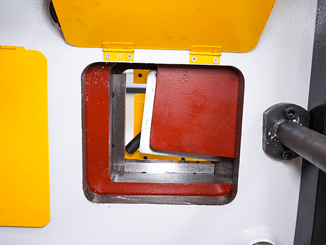
In addition to punching, the Ironworker also has the ability to shear, including angle shearing and bar shearing.
It can cut different types of bars, including flat bars, round bars, square bars, angle bars, and beams.
The metal plates are held in place between the blades through hold-downs before being cut into the final profile.
The Ironworker is also equipped with a special metal notching station, an adjustable rectangular unit, and a threading platform for performing V-shape and square grooving.
Although the bending capability of an Ironworker may not be as precise as that of a press brake, it can still be used to bend some banisters, supports, and other low-accuracy requirement applications.
How Does an Ironworker Work?
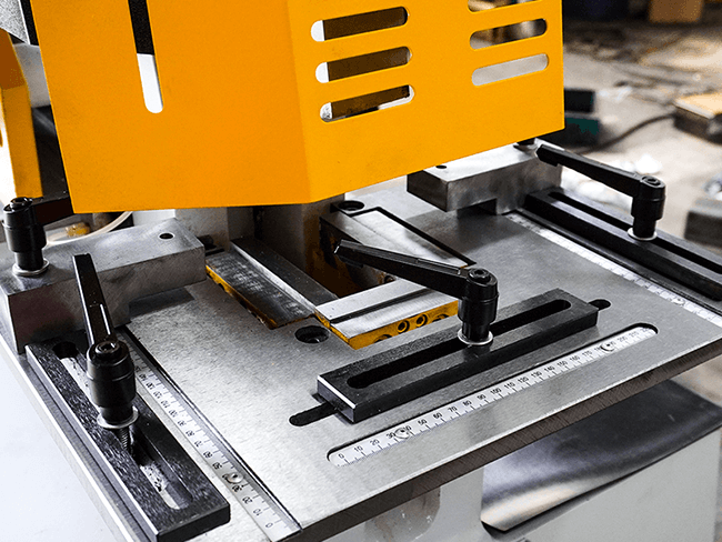
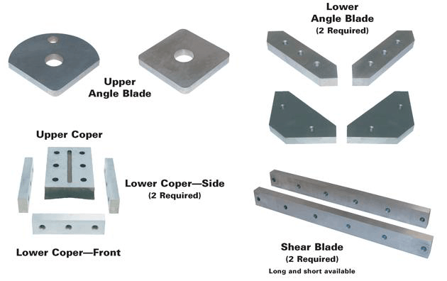
The Ironworker machine is equipped with 5 different workstations and standard tools, allowing for separate punching, rebar shearing, sheet metal shearing, corner shearing, slotting, and more.
The Ironworker machine consists of a punching station, angle cutting station, bar cutting station, notching station, and shearing station.
Each workstation is equipped with a hold-down device to properly position and fix the material in place.
The machine operates using a power system that drives the blade on the ram to move up and down for shearing purposes.
Each workstation has corresponding upper and lower molds, usually made of diamond or other materials.
The Ironworker machine is highly efficient and produces good cutting quality, capable of cutting angle steel, channel steel, square steel, round steel, flat steel, and flat angle steel.
The hydraulic Ironworker machine can control the stroke and speed through a hydraulic cylinder drive, resulting in a flexible movement of the shaft.
The mechanical Ironworker machine, on the other hand, drives the blade or punches up and down through the use of a flywheel and crank.
What Are the Components of Ironworker
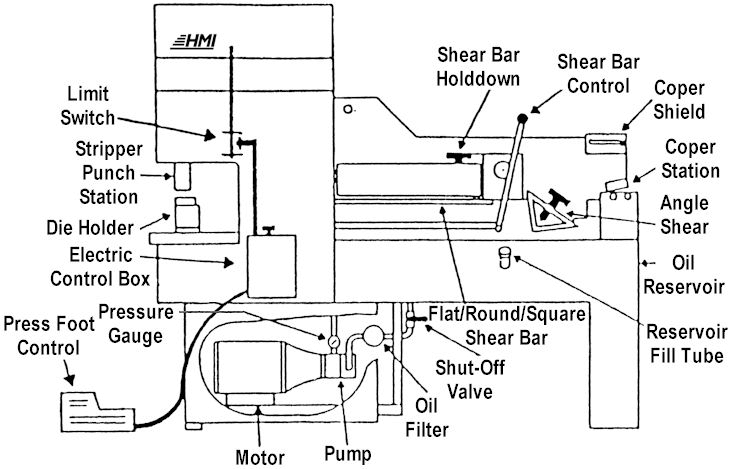
The ironworker's frame serves as the body that holds the drive system, ram, and other components in place.
It must be strong enough to prevent breakage or deformation during operation.
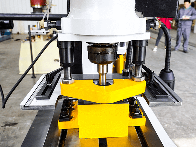
The worktable is used to support the materials for cutting and notching and also as a location to fix the punching hole at the punching station.
The ironworker also features a "hold-down" clamping device near the shear blade to secure the shearing material and prevent movement.
The hold-down can also be used to insert the material as a wedge between the upper and lower blades, increasing the gap.
The ironworker's blade, made of durable and sharp tool steel, is used for grooving and shearing.
It is typically mounted on the ram and workbench at appropriate intervals, ensuring that the edge of the sheared workpiece is clean and smooth.
The ironworker's control device includes a control lever, control button, and foot pedal.
Additional features, such as a CNC gauging device, hydraulic cooling system, custom tooling, light curtain, and guard fence, can also be included on the ironworker.
How to Determine the Capability of the Ironworker?
The Ironworker comes in different sizes and capacities, also known as tonnage.
The range of capacities extends from tens of tons to hundreds of tons, and the plates that can be cut and punched are becoming thicker.
Before choosing the tonnage, it's important to determine the maximum plate thickness, the maximum thickness of punching materials, the largest diameter of punched holes, and the maximum thickness and width of angle and channel steel.
When punching, the throat depth of the Ironworker must be at least half of the material's width.
The tonnage required for punching may vary depending on the tensile strength of different materials and should be increased by 50% accordingly.
The necessary tonnage can also be determined using the machine specification and tonnage chart provided by the manufacturer.
Conclusion
The Ironworker machine is a versatile, flexible, and efficient machine. If you're in the market for an ironworker, consider our offerings at ADH.
As a manufacturer of sheet metal processing equipment, we offer a variety of machines, including press brakes, fiber laser cutting machines, shearing machines, and ironworkers.
For more information on our ironworkers, please visit our "Contact Us" page on our website.
At ADH, you'll have a wider selection of products, competitive prices, and exceptional after-sales service.
FAQs
What Is the Hydraulic IronWorker Machine?
The hydraulic ironworker operates using a hydraulic device that powers the movement of the machine's ram and blades.
It comes in two types: one-cylinder and dual-cylinder operation.
The hydraulic ironworker offers adjustable stroke and speed and has a flexible shaft movement.
The dual-cylinder hydraulic ironworker features two independent hydraulic pistons that can be used for a range of operations, including punching, forming, shearing, and grooving.
This type of ironworker can be operated by two people and has more complex functions compared to the one-cylinder operation.
What are the Benefits of Using an Ironworker Machine?
The ironworker is a multi-functional machine capable of cutting, punching, bending, and shaping bars, flat steel, and angle steel. Its processing technology is highly efficient and accurate, leading to reduced material waste with long-term use in production.
With its different functional workstations, productivity is improved and the cost of purchasing multiple machines is reduced.
The ironworker is versatile and can handle a range of materials including stainless steel, cast iron, low-carbon steel, copper, aluminum, and others.


