I. Understanding Press Brake U Bends
The Basics of Press Brake U Bends
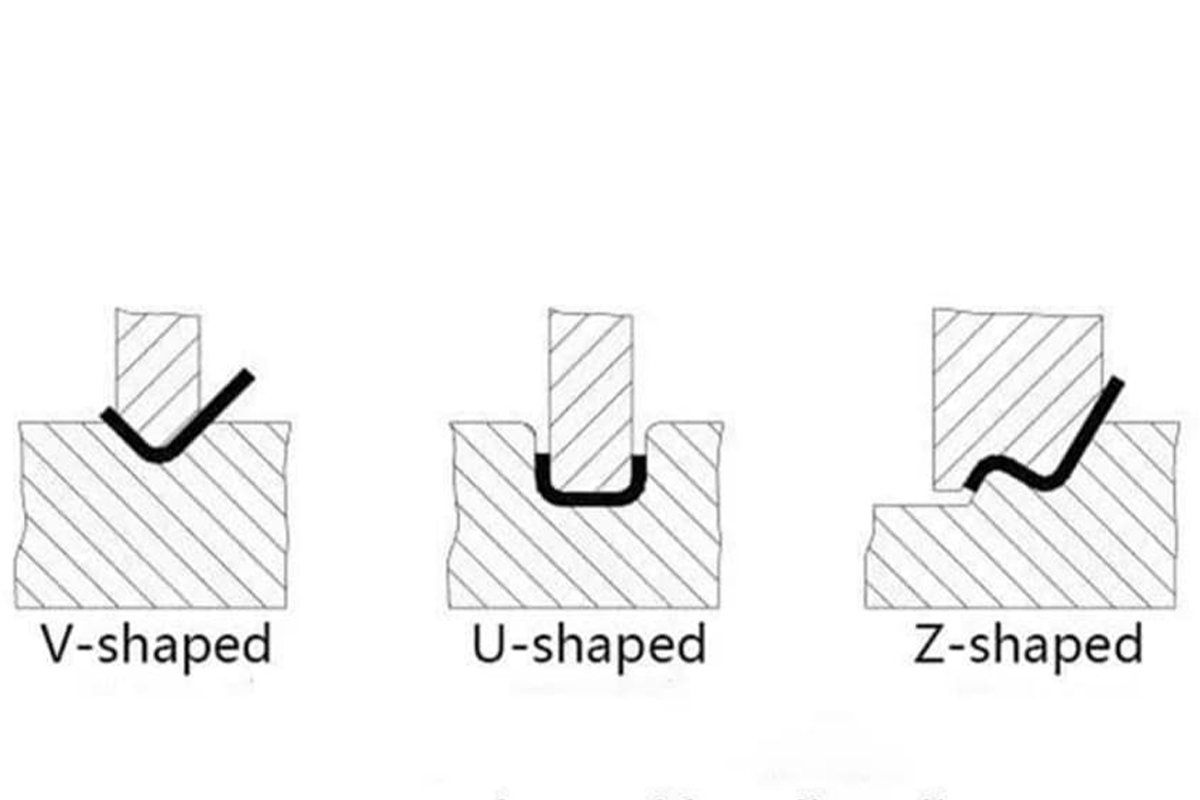
Press brake u bend refers to a process in which the metal sheet will be bent constantly on the press brake twice or more to be formed into the “u” shape.
This process is achieved by accurately controlling the closing degrees of upper and bottom dies and strokes to meet the design requirement's precise size and angle.
The u bend is one of the most common forming techniques in metal fabrication industries.
U bend is essential in various industries like metal manufacturing and mechanical engineering.
It is widely used in producing architectural and structural parts, automobile parts, home appliance casings, and design manufacturing requiring inner space like piping systems and electrical cabinets.
U bend can not only save material costs and improve production efficiency but also ensure the products' good mechanical properties and appearance quality.
History and Evolution of Press Brake Technology
The press brake is considered a pivotal sheet metal forming equipment, and its history can be dated back to early industrialization.
The initial manual press brake depends on the labor force, which features complex operation and low efficiency.
With the advancement of technology, hydraulic and CNC technology significantly improve the development of the press brake, making the machine able to proceed with precise and intricate bending, including u bend.
U bend technology is constantly upgraded with the evolution of press brake technology, which ranges from simple straight-line bending to three-dimensional bending.
Not only achieving improved apparently bending angle and precision but also realizing multi-step sequence automatic constant bending.
Modern CNC press brakes can even be integrated with CAD/ CAM software, precisely imitating and controlling the overall u bend, achieving high precision and mass production projects.
What’s more, the die technique and assistant tools, like the back gauge and front support device, also further enrich and improve the possibility and adaptability of the u-bend.
II. Technical Aspects
Types of Press Brakes for U Bending
Mechanical press brake:
Pros: simple structure, high-cost performance, convenient maintenance, intuitive operation, suitable for small scale or occasions requiring less precision.
Cons: it probably can not realize an accurate control under high tonnage owing to its movement ways restrictions. Also, it has lower working efficiency than hydraulic types and is unsuitable for mass-scale and constant production.
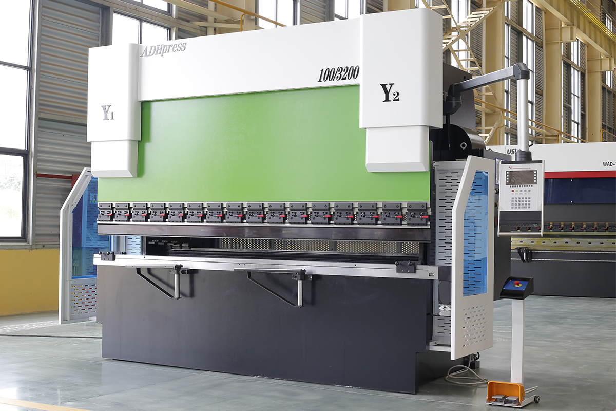
Hydraulic press brake:
Pros: the hydraulic system offers stable and intense pressure, which can be adapted to precise bending with multiple thicknesses of materials. It also can be adjusted with no levels in a more extensive range, suitable for mass production and industries requiring high precision.
Cons: the equipment is complex and requires regular maintenance for regular operation. Its initial and later maintenance costs are relatively large.
Materials Suitable for U Bends
Knowing different kinds of metal materials’ physical and mechanical properties is vital in the precise design and implementation of the u-bending process, which is beneficial to avoid product quality problems because of improper use of materials.
Low-carbon steel: it features moderate intensity good plasticity, is easy to bend, and is one of the most common materials for producing u bend.
Stainless steel: it is good, corrosive-resistant, and decorative. It requires precise calculation and control of deformation parameters during bending due to high intensity and spring-back properties.
Aluminum: it has a low density and good electrical and thermal conductivity, making it suitable for light parts. When it is bent, you should take the properties of strong ductility and small elastic modulus into consideration in order to avoid over-rebounding and influencing the product quality.
Copper alloy: it features good electrical conductivity and corrosion resistance. Due to its high solidness, it should be processed with proper dies and process conditions.
Design Considerations for U Bends
Bending radius: it is usually greater than a certain multiple of the material thickness to avoid generating cracks or over-large inner stresses during bending, ensuring the integrity of the workpiece structure.
Bending angle: it determines the final shape of the workpiece. It is calculated according to product design requirements and the spring-back effect, thus compensating and arriving at the anticipated geometric size.
Bending force: it is determined by many factors like material thickness, bending radius, and length. Overly large or small pressure may lead to quality problems. Thus, professional calculation tools and empirical formulas are needed to ensure the proper pressure value.
III. Practical Guide
Step-by-Step Guide to Performing a U Bend
Choose proper press brake and dies: choose mechanical or hydraulic press brake based on material type and thickness. Choose the appropriate upper and bottom die according to the required u-bend size and shape.
Material preparation: measure and cut the metal sheet into the required size.
Set the machine parameters: set the reasonable bending force, speed, and angle parameters according to material thickness and bending radius.
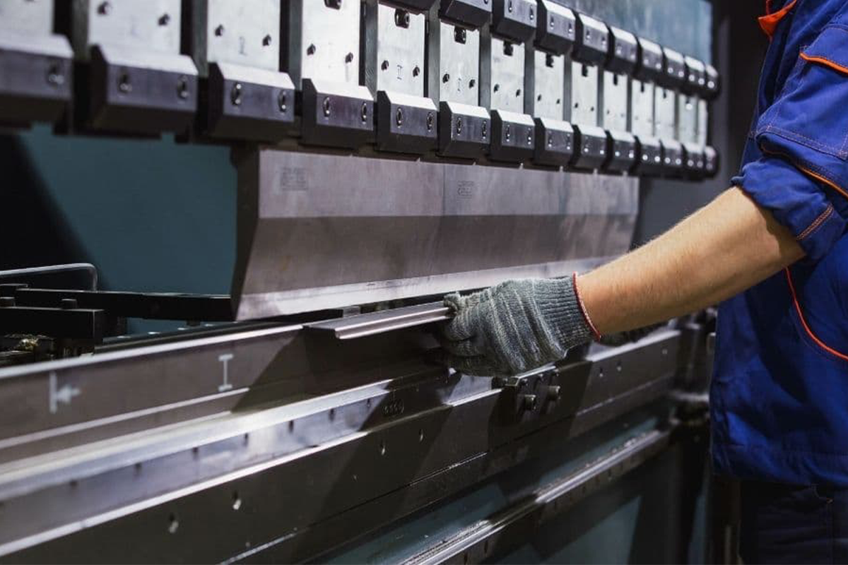
Operate the bending: put the metal sheet on the press brake, ensure it is in the middle of the die, and bend it according to the decided parameters.
Check and adjust: monitor the material deformation, check the accuracy of the size and angle, and timely adjust the pressure and angle to compensate for the spring-back effect. After one or two sides' initial bending, accomplish the other part of bending according to the same procedures.
Technique: use accurate measuring tools to verify die position and angle setting many times.
As for complex U-shaped workpieces, the step-by-step forming method can be accepted. Bend a small section at a time, and keep the section constant and consistent.
Develop standardized operating procedures, proceed strictly, and improve operational proficiency through repeat practice.
Common Mistakes and How to Avoid Them
Improper choice of dies and inaccurate die gap setting will lead to a bad bending effect or workpiece damage.
If the bending force is too large or small, this will result in the material breaking. Springback is overly large, which will affect the product precision.
Improper position of the material and fixation will lead to offset during the bending process.
There are some approaches for precautions based on the above questions:
Strictly obey the operational manual, choose the die integrated with practice experience, check regularly, and adjust the die gap.
Calculate the bending force according to the material properties and thickness, and also take the spring back into consideration, appropriately increasing the compensating volume.
Enhance the operator training and improve the material clamping and positioning accuracy.
Maintenance and Care of Press Brake Machines
Daily maintenance
Regularly clean the inner and outer debris of the press brake, ensure the lubricating system is smooth, and supplement or replace the lubrication oil in time.
Check the hydraulic system seal properties to avoid oil leaking, ensuring hydraulic components work correctly.
Maintain and check the electricity control system, ensuring the components work stably and safely.
Check the die's abrasiveness situation, grinding, repairing, or replacing the new dies when necessary.
Long-term maintenance strategies
Develop detailed equipment maintenance plan, check and repair regularly, to prevent potential malfunctions from happening.
Establish the using record, and track the equipment operation condition, to offer evidence for later maintenance.
Raise employees' awareness of the importance of equipment maintenance, and develop a good operation habit, to prolong the press brake lifespan and working efficiency.
IV. Industry Applications
U Bends in Various Industries
Automobile industry
In automobile manufacturing, u bend is widely used in producing exhaust system ducts, suspension components, and body structural parts. It is strict for the material chosen, bending process precision, and products’ durability because these components usually need to bear high temperature, high pressure, and vibration.
Aerospace industry
The aerospace industry has extremely high requirements for lightweight and high strength. U bend process is usually used in aircraft fuel delivery systems, fuselage frame structures, and other internal pipeline layouts, ensuring each part can meet strong standards and achieve weight loss goals.
Architecture industry
In the construction industry, u-shaped steel or tubes are widely used in structure support, exhaust systems, HVAC piping, etc. Especially in steel structure architecture, pre-bent u-shaped beams can improve working efficiency and structure stability, which is convenient for spot assembly.
Future Trends in Press Brake U Bending
Emerging technologies and methods
CNC technology and automation degrees are constantly improved, making the press brake able to accomplish more complex U-shaped bending tasks, and decrease the error brought by the manual intervention.
The machine technology and intelligent production system are brought to make u bend more efficient, flexible, and adapted to small-scale, sorts of varieties and custom production needs.
Material science development, like the emergence of new composite materials, will challenge the press brake process, and also provide u bend technology with the possibility of innovative applications.
Metal fabrication industry anticipation
Future press brake technology will stride to high precision, faster speed, and large flexibility to handle the more complex workpiece design.
The concept of green environmental protection is deeply rooted in the people's hearts. The equipment and technology with low consumption, and high production will be the mainstream, including the application of the energy-saving hydraulic system, recycling of waste heat, and other measures on the press brake.
Digital and network technology will further be integrated into the metal forming process. The production process will be improved by the Internet of Things, and Big Data Analysis, thus improving the overall production efficiency and quality.
V. FAQs
What is the ideal metal thickness for a U bend?
The ideal u-bend metal thickness has no fixed value and is determined by many factors, like types of press brake(mechanical or hydraulic), material properties, die opening size, and minimum bending radius.
Generally speaking, the common metal material like low carbon steel, its bending radius is usually 1-2 times or more than the material thickness, under the circumstance of no cracking or keeping a good appearance.
Can U bends be automated? Pros and cons
U bend can achieve automation in many production environments.
Pros:
Improve production efficiency: automatic press brake can work constantly, reducing human intervention time.
Improve precision: the automation system can accurately control the pressure, speed, and angle, reducing the production error rate.
Reduce labor intensity: reduce human repeatable labor, and improve working environment and safety.
Cons:
High investment: the initial investment in purchasing automatic equipment is high.
Complex maintenance: the repair and maintenance of automatic press brakes need professional knowledge and technology support.
Low flexibility: it is relatively large to adjust automatic production line cost and time for products with small-scale and multiple varieties.
What are the safety precautions for U-bending?
Use personal protective equipment: wear safety goggles, dust mask, protective gloves, etc., to avoid metal fragments splashing and inhalation of dust.
Check before operation: ensure all the press brake and surrounding tools lie in a common state. The die is stable and its setting is correct.
Correct loading the materials: avoid single-hand operation, using professional tools position and fix the sheet, in order to avoid sheet sliding or popping during bending.
No overburden operation: obey the maximum loading restriction of the equipment strictly, thus preventing the machine from damage or human injury because of overloading.
Equipment maintenance: maintain and check the press brake regularly, eliminating faults and hidden dangers promptly.
Safety training: all the operators must be trained with professional safety regulations, and know the equipment functions and emergent measurements under emergent situations.
VI. Conclusion
Our passage deeply talks about the various aspects of press brake u bend, ranging from technique details, practical guidance, and industrial application to future trends.
Here, we encourage all the readers to practice and optimize the u-bend technique to achieve more quality products.
Welcome to browse ADH machine's official website, which constantly focuses on industry vibration and technique advancement to adapt to changing market demands and challenges.


