I. Introduction
Brief history and evolution of laser cutting technology
The laser-cutting machine laid the foundation for laser processing. In 1964, successive inventions of the YAG solid laser and CO2 gas laser were the main providers of early light sources.
During the 1970s, the first generation of industrial laser-cutting machines was invented. Mainly adopted CO2 laser, it was used to cut sheet metal.
At that time, laser cutting started being applied in many sectors, including vehicle, aviation, and machine fabrication, with characteristics of high accuracy and speed, and narrow slits.
At the beginning of the 21st century, Fiber laser cutters used in the cutting sector promoted laser cutter updates and innovations.
After the 2010s, the industry embraced the era of ultra-high power. In 2017, the first laser-cutting machine possessing 12kw was launched, marking the entrance of this era.
Importance of understanding laser cutting procedures
As an advanced machine tool for manufacturing, laser cutting machines play an irreplaceable role in promoting transformation, upgrading the manufacturing industry, and improving quality and efficiency.
Knowing of the laser cutting procedures can help us:
Firstly, safety and accuracy in the cutting process are critical. If not operated properly, the machine may do harm to operators.
So, if we know the operating process of the laser cutter, it’s an efficient way to protect operators and maintain the machine itself.
Second, knowledge of the laser cutting process and machine operation allows optimal performance and cutting quality. Learning with these parameters helps achieve the desired results.
Troubleshooting common cutting defects occurs from time to time. Trouble-resolving relies on operator knowledge.
Recognizing problems like dross, burrs, or incomplete cuts and knowing how to adjust parameters to resolve them is proven as an important skill in the process.
II. How Laser Cutting Machines Work
Definition and work principles
At the beginning of the article, let’s start with some easier concepts. First, what is a laser cutting machine, and then how does it work? Knowing this helps us pave a path for further understanding.
What is a laser cutting machine? Here is a video I have prepared for you to enjoy.
After watching it, we could get a basic understanding of a laser cutter. It’s time to dig deeper. Our company will explain it to you in detail.
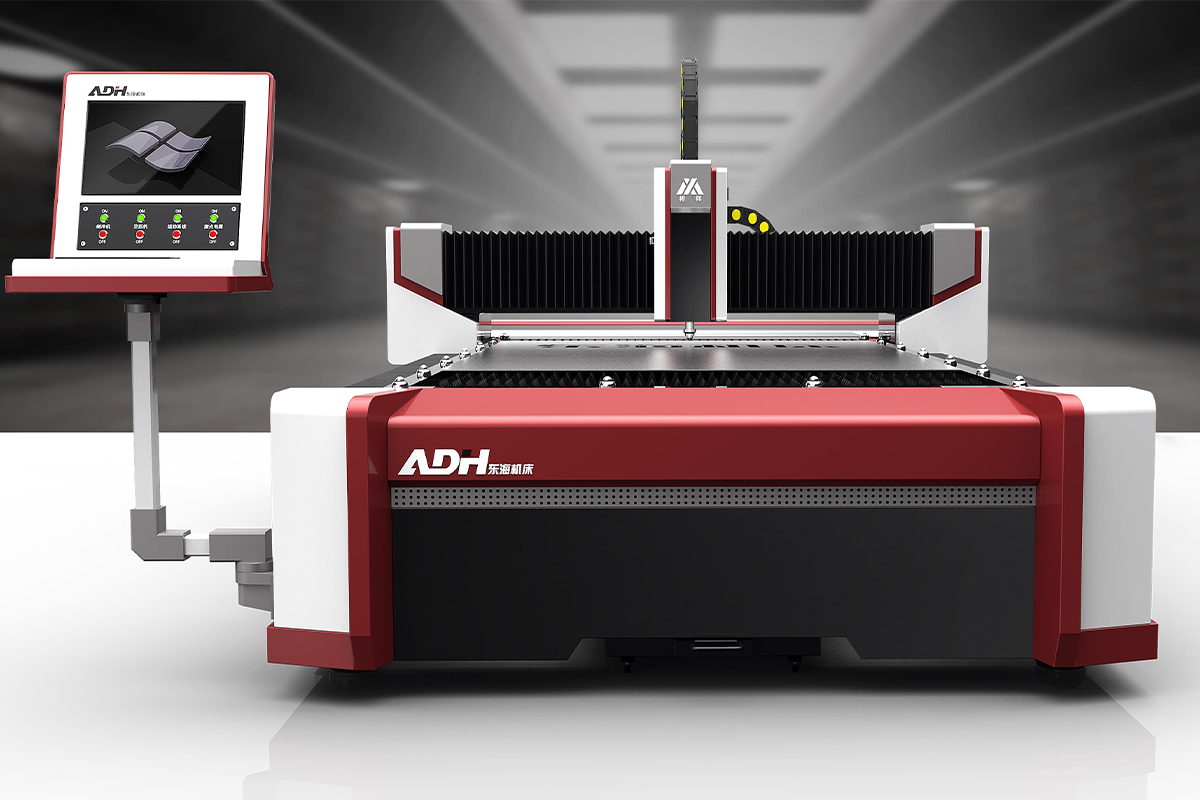
A laser cutting machine, a kind of thermal cutting equipment that uses a laser beam with high power and density to irradiate metal, can quickly melt, vaporize, or ignite metal while blowing off molten matter with beam coaxial high-speed airflow so as to achieve cutting. It’s one of the widest-used processing equipment in industrial fabrication.
Now that we have acquired the concepts of laser cutting machines, you might want to know how they work. Its operation principles will be explained in detail as follows:
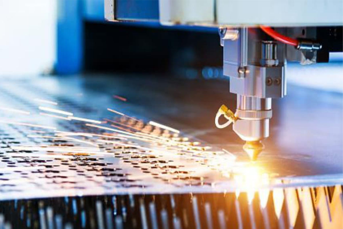
The laser cutting machine’s laser beam will be focused into a small spot by a focusing lens, making the focused spot reach a high power density.
When a light spot is cast onto the surface of the workpiece, the material temperature of the focused area will climb immediately, so the material starts melting and vaporizing.
As a result, a cutting point was formed. As the moving of cutting head, the cutting points are linked into a narrow slit to cut the material.
Types of laser cutters used (CO2, Fiber, etc.)
According to different standards, laser cutting machines can be divided into various categories.
However, in our article, they were mainly divided according to production types, including CO2 laser cutting machines, YAG (solid) laser cutting machines, and Fiber laser cutting machines.
Fiber laser cutting machine: as the mainstream of the marker, it adopts Fiber lasers as light sources, figuring high cutting quality, accuracy, and efficiency.
A CO2 laser cutting machine is a laser cutter that uses CO2 gas to cut metal and non-metal material. It can stably cut carbon steel within 20mm, stainless steel within 10mm, and aluminium alloy within 8mm.
YAG (solid) laser cutting machine: Though it was cost-effective and steady, the market phased it out because of its low efficiency.
Laser cutting vs traditional methods: precision, speed, versatility, cost-effectiveness
The article mainly compared the laser cutting machine with traditional cutting methods in terms of precision, speed, versatility, and cost-effectiveness so as to know the advantages of the laser cutting machine intuitively.
| Comparative object | Laser cutting machine | Traditional methods |
| Precision | Able to achieve high-precision cutting of ±0.1mm. Smaller heat-affected zone, minimizing material deformation | Lager heat-affected zone, impacting the quality of material Low accuracy |
| Speed | Faster than traditional methods. The cutting speed of materials below a certain thickness (about 10mm) is better than that of plasma or flame cutting. | Slower than laser cutting Having an edge upon plasma or flame cutting. |
| Versatility | Allowing for a broader range of materials, thicknesses, and shapes | Limited in materials, thicknesses and shapes |
| Cost-effectiveness | High investment initially;low long-term operating costs. Higher accuracy and faster speed | Low investment initially; more waste and lower efficiency |
III. Step 1:Preparing for Laser Cutting
Cleaning lenses and mirrors
Before using a laser cutter, we first clean the lenses and mirrors. Because a large amount of dust created during the cutting will accumulate on the mirrors and focusing lenses, resulting in power loss and damage, cleaning is a critical part of preparation.
When cleaning, we should dip a cotton swab into an acetone or alcohol cleaning solution and then wipe gently. Start with the centre of the mirror and then slowly rotate a circular pattern to the outer edge.
Inspecting and replacing consumables if needed
Consumables for laser cutting machines mainly include laser tubes, auxiliary gases, lenses, etc. The status of these consumables needs to be checked regularly to avoid affecting the cutting effect.
This is also a critical procedure of laser cutting to improve cutting accuracy and efficiency. The lifespan of laser-cutting machine consumables is generally measured in months.
Powering on the machine and chiller unit
Before using the laser cutting machine, you need to turn on the power and chiller. However, you should notice that:
Check supply voltage
Before use, check whether the power supply voltage complies with the machine’s rated voltage to avoid unnecessary damage.
Check chiller status
Before use, the status of the chiller should be checked. For example, if there are problems caused by accumulated dust, clogged pipes, and insufficient cooling water, you need to solve them in time. After turning on the power of the chiller, check whether the pipe joints of the chiller are leaking or seeping.
Check the pressure and temperature of the cooling water
The cooling water temperature is kept preferably with the desired temperature of the selected laser.
Check the external light path control switch
Check if the control switch of the external light path above the chiller is opened. The external light path should be inspected once a month to two months.
Homing axes and resetting the origin
The aim of this step is to return each motion axis of the machine to the mechanical origin or zero point.
IV. Step 2: Creating and Importing Design File
Creating design files and exporting them in vector format (DXF, AI, etc.)
In this step, related software can be used to build design files for laser cutting, including vector pattern design software, CorelDRAW(CDR)、Illustrator(AI)、AutoCAD.
Input or export in the cut pattern to ensure the accuracy of design and set sizes and parameters as laser cutter required.
Export the graphic files completed in the design software into a format that can be recognized by the laser cutting machine. Common ones include PLT, DXF, A, etc.
Check whether the exported file is complete and whether there are any extra lines, text, etc., so as not to affect the cutting.
Importing files into laser cutter control software
Copy the exported design file to the computer connected to the laser cutting machine, usually through a USB flash drive. Open the supporting laser cutting control software, select the import file, find the design file, and open it.
Checking design size and placement
After the above steps, select the pattern and set cutting or engraving. Check the parameters, including colour, power, speed, etc.
V. Step 3: Configuring Laser Settings
Selecting the appropriate material type and thickness
Different materials, including metal, wood and plastic, need to set different cutting parameters. In addition, the thickness of materials also has an influence on its parameters for power and speed.
Adjusting laser parameters
Adjustments should incorporate power, speed, frequency, and focus distance. The greater the power it has, the stronger the cutting capacity it possesses.
The efficiency of cutting will increase with the cutting speed. However, the over-speed cutting may not cut through materials.
The higher the frequency, the smoother the incision, but too high a frequency will make the incision shallower; the lower the frequency, the deeper the incision will be.
The focus diameter affects the slit width, and the appropriate focal length needs to be set according to different material thicknesses.
Trial cutting of scrap material
Before formal cutting, you must make a trial cut on the scrap material to check the cutting effect.
Dialing in settings for optimal cut quality
When finding the most suitable combination of cutting parameters, you can save it as fixed data for an easy recipe for easy subsequent, direct calling.
VI. Step 4: Loading and Fixturing Material
Selecting flat, clean and properly sized sheet stock
Flat sheet metals ensure that the laser head is parallel with the surface of the metal to make sure cutting depth and quality. A clean one to keep quality and protect the laser head.
The size of sheet metal should match the workbench so as to avoid inconvenience.
Using weights, clamps, or jigs to secure the workpiece
To prevent the workpiece from moving while cut, proper methods need to be taken. Weights can be used to match lighter workpieces.
Clamps and jigs are more professional fixing tools that can provide steady fixing force without damaging the workpiece.
Ensuring the material is square and not warped
Before cutting, it’s critical to ensure that the edges of the workpiece are square so as to be parallel with and vertical to the coordinate axis of the cutting machine to keep the accuracy of the cutting path.
At the same time, if there are curves on metals, more fixing points need to be taken to ensure the same depth of cutting.
VII. Step 5: Running the Cutting Program
Stepping back behind the laser shield or closing the door
Before running the cutting, a final inspection should be carried out. Then operators should step back behind the laser shield or close the door because strong light and harmful smoke generated while cutting might do harm to operators.
Starting the program and monitoring the first few cuts
After all the preparations are done, the cutting process can be started. However, the first few cuts should be carefully inspected to monitor abnormal situations, ensure quality, and adjust parameters.
Pausing or stopping the machine if issues arise
During the cutting process, if any abnormality is observed, such as incomplete cutting, material catching fire, or abnormal noise from the machine, the cutting process should be paused or stopped immediately to prevent the problem from worsening.
VIII. Step 6: Unloading Parts and Cleaning Up
Carefully removing parts from sheet
Allow cut parts and scraps to cool down to avoid scalding. After cooling, carefully remove the sheet metal from the workbench. Remember the high temperature and sharp edges of the workpiece.
Cleaning cutting bed of debris
A great amount of craps and dust will be generated in cutting. If not cleaned timely, it will not only impact later cutting efficiency but damage the machine. Tools like brushes and vacuum cleaners can be used.
Properly disposing of scrap material
Waste should be dealt with carefully and correctly and sent to a recycling or disposal center as a way to protect the environment and be responsible for society.
IX. Conclusion
Knowing the laser-cutting processes plays a crucial role in machine learning. Laser-cutting machines promise a prosperous future in manufacturing.
Our company has 4 decades of R&D history for laser cutting machine. If you are interested in our products. Please click here. If you have any problems, you are welcome to contact us.
X. Frequently Asked Questions (FAQs)
What materials can be cut with a laser cutting machine?
Laser-cutting machines can cut various materials, including timber, all kinds of metal, paper or cardboard, plastic, and glass. Non-metallic materials such as rubber, leather, and acrylic can also be cut by CO2 laser cutting machines.
How thick of material can a laser cutter handle?
The thickness a laser cutter can handle depends on various elements. Generally, low-power machines( less than 1kw) are mainly used to cut thinner materials like paper, thin plastic, and sheet metal. Large-power ones(over 4kw) are capable of handling thicker materials, including thick metal plates.
What are the safety precautions for operating a laser cutter?
Before operating, you should read instructions, wear protective glasses, make sure there is no single operation, understand the nature of the workpiece, keep the cleanness of working area, adopt ventilation and filtration systems, be cautious of flammable material, and wear suitable personal protective equipment.


