
I. Introduction
Press brake bending is a common metal fabrication technology to bend metal sheets into required shapes.
It is vital in metal fabrication industries and manufacturing.
In the process of bending, the metal sheet is placed on the press brake and can be bent into the required angles and shapes by exerting pressure.
The press brake is usually made up of top punch and bottom die, and the top punch bends the metal sheets by exerting pressure downward.
This technology is widely applied in producing various products, like auto parts, home appliances, building materials, etc.
These machines can not only improve the products’ quality and consistency but also significantly improve production efficiency by slightly adjusting the precision.
The press brake has higher production efficiency and precision than traditional manual bending.
Thus, it has increasingly received attention and broadly been applied to various low-scale to large-scale production programs.
Knowing the press brake technology is vital to designing and producing sustainable, intelligent products.
II. History and Evolution of Press Brake
The term press brake dates back to Britain in the late 19th century. At that time, people used simple tie rod machinery to bend the metal sheet manually. In the early stage, this “press brake” was a simple destroyer that used manual labor to exert bending pressure.
In the early 20th century, the press brake became automated and intricate. Accompanying the industrial revolution, the hydraulic and electric systems were delivered into the machine operation. In the 1930s, the first hydraulic press brake came into view. It was equipped with hydraulic cylinders and bent automatically, significantly improving production efficiency.
Striving into the digital era, the press brake technology has been pushed forward. In the 1980s, an electronic press brake using a CNC system was brought to view. It can control the bending action precisely through computer programs, realizing automatic program bending production lines. These CNC press brakes are highly accurate, can operate complex shapes, and have become the industry standard of press brake operation.
With the advancement of technology, the press brake driven by servo motors is becoming more and more prevalent. This type of machine uses strong servo motors connected to the machine's electricity system network to manipulate the press brake arm. Servo press brake allows the user to input required shapes in the way of programming compared with CNC machines, which input the design before bending, thus achieving higher efficiency production operation.
In a nutshell, over the 200 years, the press brake has experienced a rapid change from manual labor to automation, analog to digital, creating the widespread high-efficiency intelligent technology used today.
III. Basic Components and Working Principle
The fundamental of a press brake includes c-shaped frames, a top punch, a bottom die, and a hydraulic system.
In the bending process, the workpiece is placed on the bottom die, and the top punch will bend the metal sheets by exerting pressure.
The hydraulic system controls the top punch's movement by controlling the fluid flow.
The c-shaped frame is the main body of the press brake, which supports the top punch and bottom die.
The top punch is used to exert pressure, while the bottom die is used to support the workpiece.
The hydraulic system is made up of tanks, pumps, motors, valves, and pipes, which work together to control the movement of the top punch.
In the bending process, the workpiece is clamped between the top punch and bottom die and can be bent by exerting pressure. The whole bending process is programmed and smooth.
Hydraulic systems can precisely control the application torque and bending speed, ensuring that each bending angle is even and accurate.
When bending is finished, the pressure is released, and the workpiece is removed from the die. This completes the whole process of automotive bending.
IV. Types of Press Brake Machines
The press brake features three types: hydraulic press brake, servo-electric press brake, and mechanical press brake. And each type has its own advantages and characteristics.
It is essential for you to know the machine’s differences before choosing.
Hydraulic Press Brake
The hydraulic press brake utilizes the hydraulic systems to move the top punch. The system can offer more pressure and power. Thus, bending can be more precise, and control can be better.
Compared with a mechanical press brake, these machines feature higher precision and quality, boosting steady and reliable power.
However, it has a large control force and easier to leak noise at the work site.
Servo Electric Press Brake
The Servo press brake uses a strong servo motor to drive a set of arm and lever systems, which can precisely bend the material into the required shape.
The servo motor drives the ball screw or belt drive system, thus realizing the accurate and quantification bending.
Unlike the CNC press brake, the servo-electric press brake allows users to input the required shape in the form of programming. Thus, higher efficiency operation can be achieved.
However, the system is complex, and the cost is relatively high.
Mechanical Press Brake
The mechanical press brake is operated by a mechanical transmission system driven by a flywheel and clutch.
The flywheel gains power from the motor and releases it to drive the pressure cylinder.
Because this equipment is cheaper than hydraulic equipment, so it will be a nice choice for a small-scale workshop.
However, this machine is unable to provide the precision, strength, and control as the hydraulic or electric press brake does.
The structure is simple, and the cost is relatively low. The maintenance is convenient and suitable for small-scale manual production.
It is impossible to achieve automated linear work.
V. Bending Techniques and Applications
Air Bending
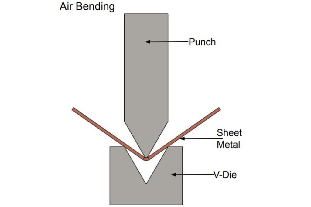
Process
Air bending is one of the commonly used technologies in metal bending, which will not make metal contact the die directly.
The punch will press the metal sheets into the die to some depth without connecting the bottom.
The reason for bending is the metal sheet lies on the top of the v-shaped die at the bottom and utilizes the bottom air gap.
The bending angle is determined by the depth at which the punch descends into the die.
The need for pushing rod force is negligible because the bending energy is generated by the leverage effect rather than the die itself.
Advantages
Air bending stands out for its versatility.
Because the metals do not utterly fit the shape of the die, thus using the same set of tools is able to achieve a bending angle, which decreases the tool changing time and improves the efficiency.
Compared with other methods, air bending needs less force, thus can prolong the machine’s lifespan.
Applications
Air bending is widely applied in the hydraulic press brake for flexibility, especially when multiple bending angles are needed in the same work.
It can be used to bend multiple metal materials and produce small-medium scale products.
Many industries have benefited from this technology, such as automotive, aerospace, and construction.
There is no need for these industries to replace the tool constantly, and can generate various components.
Bottom Bending
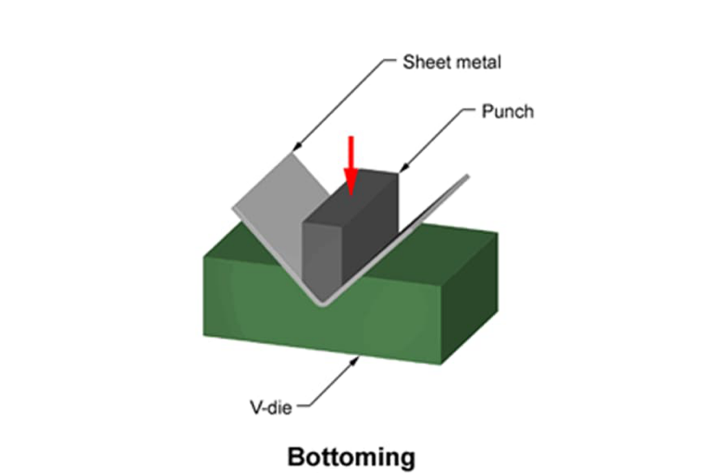
Process
In bottom bending, the metal sheets are utterly pressed in the bottom of the v-shaped dies.
The punch forces the metal to form the same shape as the die. Unlike air bending, bottom bending forces metal to the whole contact with the top of the punch and two sides of the tooling.
However, compared with coining, the exerting pressure is relatively more minor. Thus, the bending angle is hard to match the die utterly.
Rebound
The apparent phenomenon in bottom bending is “rebound”.
When the metal sheets have been bent and released, they will shrink slightly to recover to their original shape.
This elastic recovery may cause problems when the precision is paramount.
To offset rebound, the punch will bend the material excessively.
Or the die with a finer angle can be pre-adopted to bend to ensure the final bending angle is accurate in case rebounding occurs.
This method is applicable to bend parts with relatively simple geometry.
Application
Under the circumstance of emphasizing consistency and precision, bottom bending is preferred.
It is widely applied to the industry requiring minimum difference and uniform components, such as electronics.
Coining
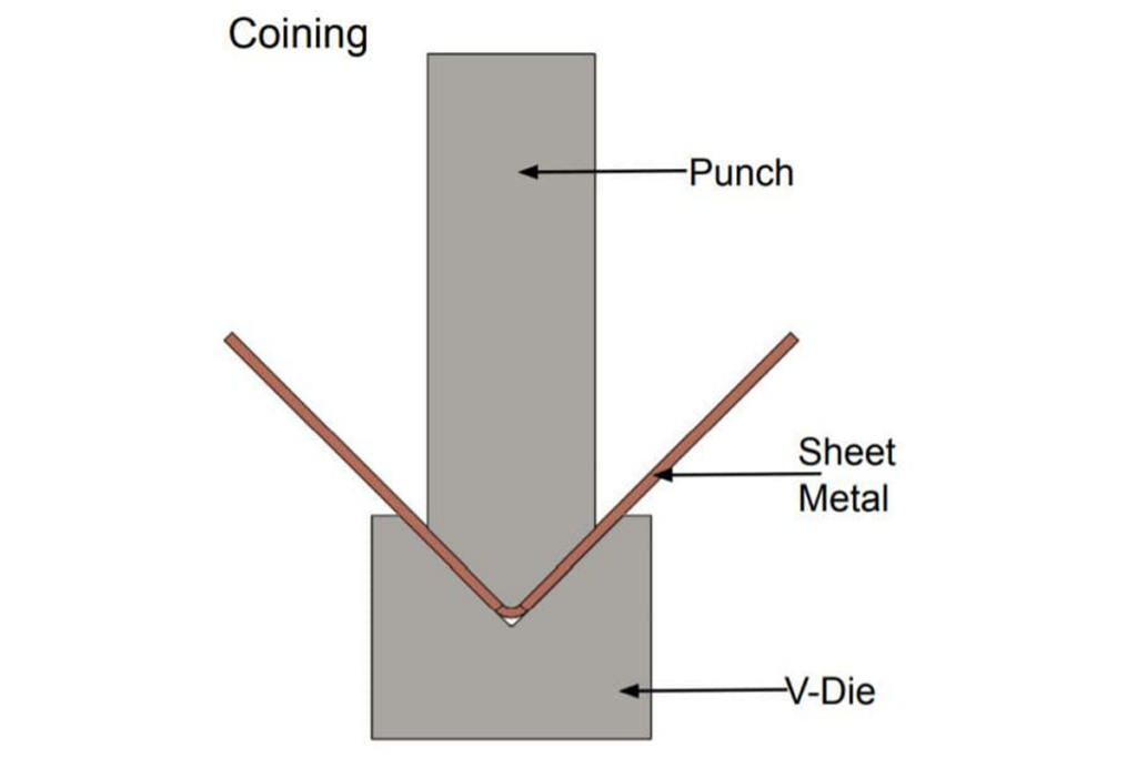
Process
Coining is a technology that uses strong power to press the metal sheet and forces it to deform, bend, and thin to precisely fit the die shape.
This process is renowned for its enormous power and will make people reminiscent of the coin’s coining process.
It requires a higher-strength press brake and a more intricate tooling design and is mainly used for components requiring high-precision production.
Relation to coin production
“coining” refers to the method of coin production initially.
In the process of coin production, the blank metal plates will be pressed between the two dies under tremendous pressure, thus ensuring the metal flowing and die filling.
A coin with a complex design will be produced. Similarly, the metal will be pressed in coining technology to capture each mini detail of the die.
VI. Advanced Technologies in Press Brake Bending
Press brake bending is a widely used metal forming process involving the elastic deformation of the metal sheets under the pressure of press brakes' top punch and bottom die and plastic deformation.
The press brake adopts many advanced technologies, and CNC is the one. Through CNC technology, the press brake operation does not utterly rely on manuals. Instead, the preprogramming is advanced.
This means the construction and operators can design and input the specific parameters on the computer.
The machine can be operated according to these instructions. The benefits of using CNC in press brake are as follows:
Precision improved: the CNC technology can control the bending process precisely, thus achieving accurate and consistent bending.
Repeatability: due to the machine being operated by pre-designed programs, each bending can achieve highly consistent results, regardless of the production quantity.
Productivity improved: the automotive operation reduces the need for human manipulation. CNC machine tools can achieve intricate bending operations with high efficiency, decreasing production time and improving productivity.
Flexibility: CNC technology allows the users to modify and adjust the bending parameters easily to adapt to the different task requirements.
Setting time reduced: CNC machine tool can restore and recall bending programs without manual setting, reducing the transition time between the workpieces.
Waste reduced: high precision and repeatability mean fewer errors and wastes, thus reducing materials and costs.
These advanced technologies utterly transform the press brake bending process, making various industries more efficient and cost-effective.
VII. FAQs
What are the fundamentals of bending metal with press brakes?
The fundamental of bending metal is to place the metal sheet on the press brake and exert pressure on it to transform it into required shapes. The press brake is made up of the top punch and bottom dies.
The top punch exerts pressure to bend the metal sheet, and the sheet is fixed by the bottom die.
This process is widely used in various industries, such as automotive, electrical appliances, and construction, to manufacture a variety of products.
It offers high-efficiency production programs and ensures the accuracy and consistency of the final products.
Its bending technology is determined by factors like bending material, thickness, and required shape.
The manufacturing can achieve precision and high-quality results in metal fabrication through knowing the fundamentals of press brake bending.
What is the rule for bending metal?
The rule of bending metal is influenced by multiple factors, including bent materials, thickness, and required shape.
Generally, the interior bending radium equals the thickness of the material being formed.
For example, if you need to bend a metal sheet of 1/8", please use the tool with radium of 1/8" to create the bending interior.
If you want to bend the material with a thickness of 0.020", please use radium of 0.020".
The minimum bending radium is determined by the bending material’s ductility and resistance to fracture.
The material supplier’s product data sheet outlines the extent to which the sheet can be formed without trouble and will recommend the minimum bending radium according to the material type and properties.
When using the sheets, it is essential to pay attention to whether shaping is in the direction of the grain (longitudinal) or crosswise (transverse).
At what temperature does metal start to bend?
When shaping the thick sheet with narrow bending radium, the material should be preheated between 200 and 300 degrees Fahrenheit, especially when bending the sheet of 0.75’’ or more. However, the temperature of initial metal bending is determined by several factors, including the bent material, its thickness, and required shapes. When determining the proper bending temperature, it is vital to calculate the material’s chemical ingredient, surface and edge state, and thickness.
VIII. Conclusion
Nowadays, press brake bending is indispensable for metal manufacture.
This process is renowned for its long history, advanced technology, and widespread use, which makes it pivotal in various industries like aerospace, automotive, and construction.
The applications of CNC technology make the press brake bending significantly improved.
It is essential for you to choose experienced manufacturers to delve into this technology and its back mechanical manufacturing.
As a leading company with over 40 years of press brake manufacturing experience, ADH Machine Tool can provide you with the most professional solutions and consultation.
If you want to inquire about the machine's price or want to learn more about the press brake knowledge, you can browse our product website or contact us directly.
Let us work together for the future of manufacturing.


 English
  Arabic
  German
  Spanish
  French
  Portuguese
  Japanese
  Russian
  Chinese