The dial indicator reveals everything. When its needle moves across the lower die holder and shows thirty-two thousandths of an inch of runout on a machine that’s supposed to be new, the damage is already done. The shop owner had just placed a $100,000 press brake on his floor, tightened the anchor bolts with an impact gun, and connected the wiring. He assumed he was building a sturdy workstation. In reality, he had permanently deformed a massive cast-iron frame.
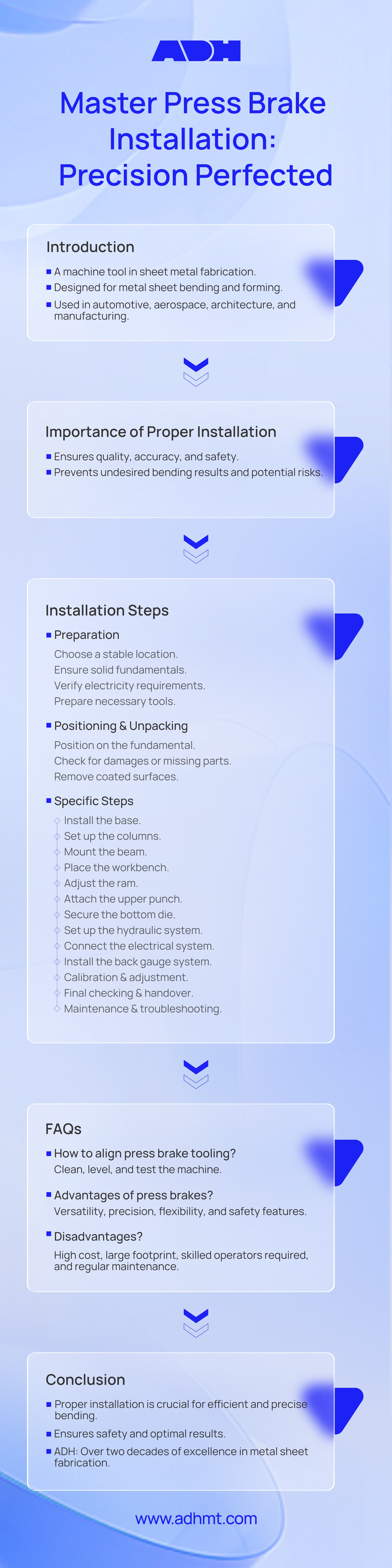
After twenty years of fixing poorly executed shop-floor setups, I witness this same situation almost every month. Installing a press brake isn’t a straightforward mechanical assembly—it’s a precise calibration process where skipping unseen steps like frame settling, multi-axis leveling, and thermal drift compensation can irreversibly warp your machine before the first bend is made.
Related: How to Install Press Brake Dies
The "Plug and Play" Myth: Why Assembly Is Not Installation
The Risky Assumption Embedded in Every Generic Instruction Guide
Open a standard installation manual, and step three often says: "Place a precision level on the machine bed." It appears intuitive—the bed is large, flat, and conveniently positioned. Yet if you calibrate your axes against the bed, you’ve already guaranteed the production of defective parts.
For a deeper breakdown of how this principle translates into real installation results, ADH Machine Tool details each calibration stage in its article on how to properly install a press brake, developed from its ongoing R&D in CNC press brake and automation technologies.
The only true reference surface for all measurements is the precisely machined mounting face of the lower die holder.
The bed merely serves as a structural support. It contains microscopic irregularities from casting and machining. The die holder, by contrast, is the interface where the tool meets the material. Leveling to the bed instead of the die holder creates a skewed baseline. Every further calibration—the backgauge alignment, ram parallelism, and crowning correction—may be mathematically precise yet referenced to a flawed origin. You end up carefully adjusting an inherent error.
Could You Be Bolting Down a Distorted Frame Without Realizing It?

You position precision shims under the jackscrews to bring the die holder into perfect level. The bubble stays centered. You reach for the impact wrench to tighten the anchor bolts. Stop.
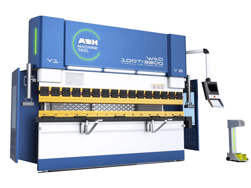
If you tighten those bolts while the jackscrews carry the load, you transform your new press brake into a torsion spring. The machine’s weight remains supported by the hard points of the jackscrews, not the floor. To complete the installation correctly, you must loosen the jackscrews and allow the multi-ton cast-iron frame to settle naturally onto the shims. For installations where alignment precision directly affects throughput, consider the intelligent control and frame-stability design of ADH Machine Tool’s CNC Press Brake, engineered to deliver accurate bending and reliable long-term performance.
This is the "drop and wait."
Cast iron is extremely heavy yet not completely rigid—it can flex. When you skip the settling step and tighten the anchor bolts immediately, you force the frame to adapt to any microscopic unevenness between the jackscrews and the floor. This causes the metal to twist. The distortion is invisible to the naked eye, but the hydraulic cylinders detect it, contending with the warped frame on every downstroke. This accelerates seal wear and makes consistent bend angles unattainable.
The Warranty Trap: Which Steps Truly Require a Certified OEM Technician?
Modern press brakes appear remarkably advanced. Upon startup, precision linear scales initiate a preset auto-homing process—typically, the Y-axis (ram) ascends first, followed by the X, R, and Z axes of the backgauge.
This integrated automation can foster false confidence. Since the machine calibrates its own zero points, many shop owners assume physical alignment is less critical. If the controller reports that the ram is parallel, they take it at face value. Yet software cannot correct a mechanically twisted frame—it merely compensates until the structural strain surpasses operational limits.
That is the moment when the warranty trap closes.
If you bypass the manual multi-axis leveling and rely solely on auto-homing, your initial inaccurate bends will look like software errors. You may call the manufacturer, claiming a faulty controller. When the OEM technician arrives, they will set a dial indicator on the lower die holder and demonstrate that the frame is twisted by thirty thousandths of an inch. Because you fastened down an unseated frame, your warranty is void. The machine is irreversibly damaged—not due to missing certification, but because software was trusted to perform a mechanic’s task. The machine’s longevity ultimately hinges on how its cast iron feet engage with your shop’s concrete floor.
Steps 1–3: The Concrete Reality Check and the "Drop and Wait" Procedure
Can Your Floor Support Full Tonnage? (The Load Assessment Most People Skip)
Typical 6-inch shop concrete provides about 3,000 to 4,000 pounds per square inch of compressive strength. To the casual observer, this seems indestructible. Yet a 15,000-pound press brake exerting 100 tons of bending force channels that immense energy into four steel pads roughly the size of dinner plates. When the ram bottoms out, this dynamic load can turn an unverified slab into a microscopic springboard.
Many shop owners assume a floor is adequate if it does not visibly crack. In reality, concrete flexes long before it fractures. If the floor deflects even ten thousandths of an inch (0.010") under the left pad during a heavy bend, the frame twists dynamically. You will endlessly adjust crowning and shim dies, unaware that the ground beneath the machine shifts on every downstroke.
Riggers will position the machine wherever directed, but they are not structural engineers. They do not verify whether the slab’s rebar grid, soil compaction, or depth can withstand dynamic loads. Before the delivery truck enters your bay, you must consult architectural drawings or take core samples to confirm the slab’s dynamic load rating. If the concrete cannot resist the machine’s full tonnage without deformation, no amount of precision leveling will salvage your parts. Once you have confirmed the floor’s capacity, the next question is how to properly set down the machine.
Shim Placement Before the Machine Touches Down: Why Sequence Takes Precedence Over Precision
Observe a rushed rigging team, and you'll often see them randomly wedge steel shims under the leveling pads as the crane lowers the machine. Their sole aim is to get the base "close enough" to level so they can unhook the chains and move on to the next job. But allowing the machine’s weight to settle onto an uneven, careless shim arrangement immediately induces a permanent twist in the cast iron.
Calibrating ram parallelism—which will later be measured at five points using dial indicators—demands a baseline entirely free of mechanical distortion. If the rear left pad lands on a thick shim stack while the front right pad is slightly suspended, the heavy cast iron will sag diagonally to close that gap. Although this sag is invisible, your dial indicators will eventually reveal a 0.02mm/m deviation that no software offset can compensate for.
At this phase, sequence is far more important than achieving a perfect level. You must first place the main load-bearing shims under the primary side frames, ensuring uniform contact, before addressing any auxiliary supports. Following this intentional sequence keeps the frame from twisting under its own weight when the crane’s tension is released. But once the hooks are off, can you immediately pick up your wrenches and begin adjusting the axes? In high-tonnage setups, that same sequence logic applies to multi-machine synchronization—solutions like the ADH Machine Tool Tandem Press Brake leverage advanced CNC control to align dual frames with precision across large bending widths, ensuring the installation work you’ve just completed translates into consistent forming accuracy.
The 24-Hour Rule: How the Cast Iron Responds After the Riggers Leave
Certain modern installation guides suggest you can skip waiting periods altogether. They promote "dynamic centralization," a step-by-step jacking and shimming process meant to achieve precise alignment immediately once the machine reaches the floor. This is a risky half-truth that places the riggers’ timeline above fundamental metallurgical principles.
Cast iron retains stress. For weeks, your press brake has been strapped to a flatbed, suspended from cranes, and exposed to varying outdoor temperatures. When the lifting chains finally relax, the metal does not instantly return to equilibrium—it creeps and settles gradually. If you begin adjusting leveling bolts minutes after landing, you are calibrating a frame that is still in motion as it stabilizes.
You must apply the "drop and wait" procedure: let the machine rest on its initial shims for a full 24 hours. This required pause enables the cast iron to discharge stored kinetic stress and adapt to your workshop’s ambient temperature. Even after waiting, the iron needs a 30–60 minute hydraulic warm-up to reach thermal stability before any measurement. Skipping this unseen step ensures your first readings will shift by the next morning. Once the iron has reached its true equilibrium, how do you achieve exact multi-axis alignment?
Steps 4–6: Multi-Axis Leveling (The Distinction Between "Bolted" and "True")
After 24 hours of rest, the cast iron has released the kinetic stresses of transportation and rigging. You are now ready for precise, multi-axis alignment. But how can you ensure a flawless geometric baseline when turning a single corner bolt risks distorting the entire frame?

Why Using a Standard Bubble Level Guarantees Inaccurate Bends
A calibration variation of just 0.2mm might appear insignificant during an initial test piece. Extend that small angular discrepancy across ten sequential bends on a complex assembly, and it results in a cumulative 2mm deviation. The part won’t fit the welding fixture, the operator may blame the tooling, and you’ll lose days correcting software offsets. High-end press brakes are built to sustain positioning accuracy within ±0.05mm to ±0.1mm. Achieving such precision isn’t possible using tools intended for construction work.
Standard levels from hardware stores—even premium heavy-duty variants—usually have a tolerance of 0.5 mm per meter. Centering the bubble on a carpenter’s level across the press brake bed may still leave the machine warped by up to half a millimeter from left to right. This unseen twist preloads the side frames with uneven tension before the hydraulic pumps are even activated.
Precision machinist levels rated at 0.02 mm/m are indispensable for this stage. Their sensitivity is extreme—resting a bare hand on the glass vial can cause the ether inside to expand from body heat and shift the bubble. The machinist level must rest on the machined reference pads, never on rough cast surfaces, and you must wait until the fluid has completely stabilized. Once the minute deviations in the frame’s posture become visible, the question is how to adjust pitch without throwing the roll out of specification.
Front-to-Back vs. Left-to-Right: Correcting One Axis Without Disturbing the Other
Many general installation manuals present leveling as a linear checklist: set the transverse axis, move to the longitudinal left, continue to the longitudinal right, and then lock everything down. Technicians who follow this process often encounter problems. They perfectly tune the front-to-back pitch, move on to the left-to-right axis, tighten a front leveling bolt to lift a low corner, and then watch the bubble on their first axis drift completely out of range.
Geometry dictates that three points define a plane. A press brake, however, rests on at least four. Adding a fourth point introduces the possibility of mechanical binding. Changing one corner effectively creates a pivot, subtly tilting the massive frame and altering the geometry at the remaining corners. Multi-axis leveling is not a linear process but an iterative, tightening spiral of minute adjustments.
The machine must be brought to level progressively. This involves turning the front-left jacking bolt slightly, then checking both the transverse and longitudinal levels, followed by adjusting the opposite diagonal corner to balance the load. The procedure continuously chases the bubble between axes, halving the error with each cycle until the frame rests evenly on all four pads with no localized binding. Yet what do you do when leveling a bed that is intentionally designed to flex under pressure?
The Crown-Bed Paradox: Leveling a Surface Designed to Deflect
Modern press brakes employ 3+1 axis control (Y1, Y2, X, V), with Y1 and Y2 functioning as independent ram cylinders and the V‑axis serving as a crowning system beneath the lower bed. This creates a mechanical contradiction: the machine is carefully leveled even though it is built to deform deliberately. When subjected to roughly 100 tons of pressure at its center, the steel bed naturally bows downward, and the V‑axis counteracts this by pushing its center upward along a precisely calculated arc.
This leads to the mistaken belief that perfect initial leveling is unnecessary because the crowning system will correct any deflection. In reality, the reverse is true. The CNC computes its crowning curve on the premise that the bed begins from an absolutely flat, mathematically zero condition.
If the mechanical baseline is twisted due to a hurried leveling process, the CNC will apply a perfectly symmetrical compensation pattern to an uneven bed. The V‑axis will lift uniformly, but the distorted frame will cause over‑correction on one side and under‑correction on the other. The result: parts measure correctly at the center but show a two‑degree variation on the left flange. After achieving a perfectly untwisted baseline for the crowning calculations, the next concern is how long you must wait before trusting those measurements.
Settling Time After Jacking: Determining an Adequate Interval Before Rechecking
Installation manuals often describe the mechanical procedure for leveling, instructing you to adjust the jacking bolts and tighten the jam nuts, but they rarely address what happens afterward. HARSLE and other OEM documents advise reinstalling the floor anchors, yet they offer no guidance on how long the structure should be allowed to settle.
For engineers who want certainty on allowable rest times and frame recoil behavior, ADH Machine Tool provides detailed press brake and leveling specifications grounded in its CNC research and testing programs. You can review those parameters in the official ADH Machine Tool brochure.
Each time a heavy-duty jacking bolt is turned against a steel shim beneath a 15,000‑pound machine, it creates concentrated stress on the threads, leveling pad, and underlying concrete. The shim stacks compress on a microscopic level. Once the floor anchors are tightened, they pull the frame downward against the upward pressure of the jacking bolts. If you take your final level readings immediately after tightening the nuts, you are measuring a frame held in artificial tension.
This oversight in standard documentation makes it necessary to contact the manufacturer’s service department for model‑specific guidance. As a general practice for mid‑tonnage brakes, allow an additional 12 to 24 hours after locking the bolts before rechecking alignment. When you return, place the machinist levels back on the reference pads. If the bubble has shifted, release the nuts and repeat the fine‑adjustment process. Once the mechanical framework is fully aligned and stable, you face the question of how to activate its hydraulic system without damaging the pump instantly.
Steps 7–9: Hydraulics and Electrical (The High‑Pressure Handshake)
After days spent leveling the frame, waiting for the cast iron to settle, and verifying the geometry, the structure is precisely even. The next stage introduces fluid and electrical power, transforming it from static to dynamic. This moment combines mechanical patience with high‑voltage risk. Starting up a press brake isn’t simply a matter of plugging it in and pressing the start button; it involves a specific sequence that aligns the machine’s internal systems under tension. Rushing this process can destroy the very components you just invested thousands of dollars to install.

Three‑Phase Rotation: The 50/50 Chance That Can Instantly Ruin Your Pump
Connecting a large industrial machine to facility power requires linking three hot conductors—L1, L2, and L3. Because alternating current phases cycle, there is a 50% probability of wiring them correctly on the first try. If the sequence is wrong, the motor runs in reverse. On a table saw, the reversed rotation is obvious and quickly stopped. On a press brake, however, a reversed motor forces the hydraulic pump to spin backward, leading to immediate and severe damage.
A hydraulic pump turning in reverse doesn’t merely fail to move fluid—it causes cavitation. Instead of drawing oil from the reservoir, it pulls air into its dry internal cavities. The precisely machined vanes or gears depend on hydraulic fluid for lubrication. Without it, metal rubs against metal at 1,750 RPM. Within three seconds, the pump’s internal components tear apart, contaminating the lines with microscopic metal fragments and necessitating a full system replacement.
To prevent this, a “bump test” is required. Before allowing the pump to run continuously, momentarily press the motor contactor with an insulated screwdriver for less than half a second. Do not listen for pump noise—watch the motor’s cooling fan as it slows and compare its direction with the rotation arrow stamped on the housing. If the rotation is incorrect, cut power, swap any two of the three phase wires, and test again. Once proper rotation is confirmed, the next step is verifying that the fluid entering the pump is clean.
Contamination Entry Points Overlooked in Most Manuals
While most manuals caution keeping the hydraulic reservoir sealed to prevent shop dust from entering, visible dirt seldom causes proportional valve failure. The true hazard arises from unseen contamination routes during initial setup. When riggers remove the transport caps from hydraulic lines, technicians often clean the exposed fittings using available shop rags or solvents. Ordinary tap water or standard degreasers near high-pressure fittings leave microscopic mineral residues. Under 4,000 PSI, these deposits break loose, abrading the cylinder seals and producing erratic ram movements that appear to be software malfunctions.
The most critical unseen entry point, however, occurs during vacuum draw. When the pump initially primes, it generates a powerful suction before the fluid pressurizes the circuit. Even a slightly under-torqued fitting or a dry-installed O-ring allows the pump to pull a vacuum through a minute gap, drawing in ambient air and airborne silica past the seals. This air intrusion imitates a leak, though it happens under vacuum rather than pressure, so no oil drips appear. Even when the system is fully sealed, the air already trapped within the lines remains a problem.
Bleeding the Lines: The Hidden Bubble You Won't See Until the Ram Hesitates
Even a perfectly sealed press brake system contains ambient air within its extensive network of steel tubing and flexible hoses. Air compresses easily, whereas hydraulic fluid does not. If every trace of air is not purged, each micro-bubble functions as a concealed pneumatic spring inside the hydraulic circuit. Under tonnage, the fluid pushes against the bubble, which compresses, causing the ram to hesitate or descend unevenly.
Physical principles require that bleeding a high-pressure system be done slowly. Rapid pressure buildup induces adiabatic heating—the friction and compression of the fluid warm it, causing expansion. Quickly cycling the ram up and down to bleed the lines makes the fluid expand, occupying the cylinder volume and giving the false impression of complete pressurization and purging.
After about two hours, the fluid cools, contracts, and reveals the hidden air pockets, making the ram stutter again. Proper bleeding involves cycling the axes at a slow pace, holding them at the top and bottom of their strokes, and allowing two to three minutes per position for heat dissipation. Only then should the bleeder valves be opened to release the remaining air. Yet fluid pressure control is only one aspect; the valves that manage that fluid depend on an electrical reference easily disrupted by grounding issues.
Grounding Paths That Pass Inspection but Still Cause Harmful Voltage Drift
Industrial environments are full of electrical noise. Welders, plasma cutters, and overhead cranes continuously inject erratic voltage back into the facility’s electrical system. A typical building ground may meet an inspector’s continuity requirements but remains inadequate for a CNC press brake.
Accuracy demands perfect electrical references. The American Society of Mechanical Engineers (ASME) specifies that reference standards must offer high precision for controlling high-pressure equipment. The CNC controller uses a 0 to 10-volt analog signal to operate the hydraulic proportional valves. When the machine ground shares a conduit with a nearby spot welder, the ground potential can drift by as much as 1.5 volts. A 5-volt command represents “50% pressure,” but if the ground floats 1.5 volts higher, the valve receives 6.5 volts and delivers 65% pressure. The resulting irregular bending leads technicians to spend days troubleshooting hydraulic problems that stem instead from electrical ground loops.
You must install a dedicated, isolated earth ground rod specifically for the press brake, and verify with a multimeter that there is zero potential difference between the machine chassis and the control board. With the fluid fully purged of compressible voids and the electrical baseline fixed to an absolute zero reference, the physical machine is finally stable. How do you convert this perfect mechanical and fluid readiness into the CNC’s digital brain?
Steps 10–12: The Homing Sequence and Tooling Alignment
You have purged the hydraulic lines of compressible air, isolated the electrical ground from shop noise, and leveled the cast-iron frame to microscopic tolerances. The physical machine is finally stable, but the CNC controller is still completely blind. It does not know where the ram is, it does not know the angle of the backgauge, and it has no awareness of the shop-floor reality you just spent hours perfecting. Translating that physical readiness into the digital brain requires a highly specific calibration ritual, and rushing it will permanently distort your machine’s operational baseline before you make your first bend.
Waking Up the Axes Safely: Tooling Installed or Removed During the Initial Cycle?

When you first power on a newly installed press brake, the hydraulic fluid is cold, the cylinder seals are stiff, and the proportional valves have not yet settled into their flow dynamics. Press brake manufacturers require running the machine idle for one to two minutes, followed by two to three full ram strokes at low pressure. This is a mandatory hydraulic preload. Cold fluid creates mechanical binding that can mimic a physical obstruction. If you immediately command the machine to find its limits, the controller will read that sluggish hydraulic resistance as a structural boundary, instantly corrupting its internal map of the axes.
You must carry out this initial wake-up cycle with the tooling completely removed. Leaving the punch and die installed during the first power-up is a catastrophic rookie mistake. The CNC starts up with no confirmed coordinate system; a sudden pressure spike or an erratic valve response can send the ram plunging downward at free-fall speed. Without the digital safety limits active, the punch will crash into the die, shattering precision-ground steel and potentially cracking the ram clamps.
Think of this process like tuning a multi-ton concert grand piano. You do not simply bolt on the legs, strike the keys, and expect a perfect concerto. The cast-iron harp must settle, the strings must be tensioned in a highly specific sequence, and the mechanical action must be exercised before the tuner ever picks up a tuning hammer. By cycling the bare ram, you allow the hydraulic fluid to reach operating temperature and the mechanical linkages to settle into their natural resting state. Once the physical system is fully awake and moving smoothly, how does the computer actually learn the dimensions of this moving steel?
What "Homing" Actually Resets (And Why Skipping It Corrupts Every Subsequent Position)
Homing is not a software reboot. It is a strict physical alignment check in which the CNC drives every axis—the Y1 and Y2 cylinders, the X-axis backgauge, the R-axis height—until they hit physical limit switches or read a specific index mark on a glass-scale encoder. When an axis reaches that physical trigger, the controller stops the motor, records the exact electrical pulse count, and declares that specific location to be the absolute edge of its universe.
Skipping or interrupting this sequence forces the controller to guess its starting position from residual memory from the factory floor, which is entirely useless now that the machine is sitting on your specific concrete slab. If you leveled the machine perfectly but the backgauge guide rails were bumped during shipping, the homing sequence will drive the gauge block until it binds against the misaligned rail. The CNC will accept that twisted, premature stopping point as absolute perfection. Every subsequent bend you program will be mathematically flawless in the software, but physically crooked on the sheet metal.
The digital-to-physical handshake is completely unforgiving. The encoders count pulses with micrometer-level precision, but they are extremely stupid; they only know how far they have moved from the starting line. If you let the machine establish its starting line while the frame is under tension or the hydraulics are binding, you embed that error deep in the operating system. But if homing only defines the extreme outer limits of the machine's motion, how does the controller know where the actual bending work happens?
For operators who want to ensure the same flawless zeroing in their own production lines, ADH Machine Tool’s large press brakes apply finite element–verified rigidity and precision CNC control to minimize calibration drift from the first homing move onward. To discuss setup parameters or verify compatibility for your application, contact ADH Machine Tool.
Reference Position vs. Zero Point: The Distinction That Separates a Working Machine from a Confused One
Beginners constantly confuse the reference position with the zero point, which leads to hours of wasted troubleshooting when bend angles start to drift. The reference position is the machine's absolute mechanical limit, established only by the homing sequence. It is the skeleton of the machine. It never changes unless you physically unbolt and reposition a limit switch or encoder.
The zero point, however, is a floating operational baseline. It is the exact coordinate where the tip of your specific upper punch perfectly meets the center of your specific lower die. Because tooling profiles vary widely in height and V-opening, the zero point changes every time you change a tool. You cannot establish an accurate zero point until the reference position is locked in. If your machine loses its reference position because of a power flicker or a skipped homing cycle, the controller will still try to drive the ram to the old zero point. Because the skeleton has shifted, the skin no longer fits, and the ram will either stop short of the metal or overdrive and crush the tooling.
You must first command the machine to find its reference position, establishing the absolute top and rear limits of the axes. Only then do you enter your tooling dimensions to calculate the zero point. The controller uses the absolute reference as an anchor, mathematically stepping down from that anchor to locate the zero point. If the math is perfect and the reference is locked, what physical trap still remains to ruin the alignment the moment you install the tools?
Seating the Punch Fully: The Partial-Seat Failure That Looks Like a Calibration Problem
A punch held by hydraulic or manual clamps often hangs with a microscopic gap between the top of the tool and the load-bearing shoulder of the ram. It may look perfectly flush to the naked eye, but a 0.005-inch gap is enough to throw a bend angle off by a full two degrees. When you run your first test piece, the machine's massive tonnage forces the punch upward, closing that gap and fully seating the tool.
To the operator, this looks exactly like a software calibration failure. The first bend is shallow, so they adjust the digital parameters. The second bend is suddenly over-bent because the tool is now fully seated, making the previous digital adjustment completely wrong. They end up chasing a ghost, changing the CNC's baseline to compensate for a mechanical seating issue. This tightening spiral of micro-adjustments eventually corrupts the entire tool library.
Before you ever set a zero point or bend a piece of scrap, you must seat the tooling. Bring the bare ram down until the punch enters the die, apply a low-pressure pinch force—usually around 10% of the machine's maximum tonnage—and hold it there. Only while the tools are under physical compression should you tighten the manual clamps or complete the hydraulic seating sequence. By forcing the physical tools into their true operating state before the computer takes its final measurement, you eliminate the mechanical slack that destroys digital precision.
The "First Bend" Test and the 50-Hour Thermal Drift
Picture yourself tuning a multi-ton concert grand piano. You’ve stretched the heavy bass strings, seated the tuning pins, and struck the first chord—it sounds flawless. Yet, you would never immediately move that instrument onto a hot concert stage under intense spotlights and expect it to remain perfectly in tune. A press brake requires the same discipline. You have homed the axes, removed mechanical play, and seated the tooling under pressure. The machine is finally prepared to bend metal. But the instant you begin that first operational cycle, you introduce heat, friction, and dynamic stress into a system that has previously existed only in a static state. The calibration you worked so carefully to achieve is already starting to fade.
Does a Perfect 90-Degree Air Bend Mean the Work Is Truly Finished?

You remove a scrap piece from the die, measure it with a protractor, and see an exact 90.0 degrees. This is the most deceptive moment of the installation. It feels like completion—but it isn’t.
For this baseline test, you program a simple air bend on a mild-steel coupon, keeping the tonnage low. You measure the angle at the center and at both ends of the bed. If the readings match, the controller and the machine’s structure are perfectly coordinated for that particular light-duty job. You have verified that the zero reference is correct and that the tooling is properly seated.
However, a thin-gauge sample provides no insight into how the press brake behaves under high load. Operators often report machines producing flawless bends at low tonnage but deviating by two or three degrees at the bed ends when running at full capacity. This occurs because the large steel side frames physically stretch under heavy force. Declaring the calibration finished without testing deflection at full operational tonnage means accepting an illusion. The first perfect bend confirms that the machine can achieve accuracy—it does not ensure that accuracy will persist as conditions change.
Thermal Drift During the First 50 Hours: Why Day-One Calibration Will Require Rechecking
Heat alters the form of every component. As your press brake cycles, the hydraulic pump shears the oil, raising its temperature. That heat transfers into the hydraulic manifold, radiates through the cylinders, and gradually warms the upper ram.
Steel expands as it heats. A ten-foot ram that warms by thirty degrees will literally lengthen and bow. At the same time, the heated oil thins, affecting how rapidly the proportional valves respond to CNC instructions. Even high-end brakes with micrometer-precise glass scales require a test bend at the start of each shift, since daily thermal cycles can push ram accuracy beyond a half-degree tolerance. You cannot override thermodynamics through programming.
The initial fifty hours of use are the most unstable. The press brake is experiencing its first thermal break-in. Seals are settling, valves are wearing in, and the frame is expanding and contracting within its new environment for the first time. If you set your crowning parameters on a cold machine Tuesday morning, do not expect them to hold true Thursday afternoon when the oil is warm. Ongoing measurement, documentation, and adjustment of your baseline parameters are essential throughout this break-in phase.
Foundation Creep: When the Movement Comes from the Floor, Not the Machine
While the upper structure contends with thermal expansion, the base contends with gravity. You leveled the press brake perfectly in its static state. Now you are directing tons of force through the side frames and into the concrete slab hundreds of times per day.
Concrete is not an unyielding or immovable substance. Under repeated dynamic impacts, its microscopic voids compress, the soil beneath the slab settles, and the steel shims you carefully positioned sink deeper into the floor. This process is known as foundation creep, and it cannot be avoided. During the first week of heavy production, the floor will settle slightly, causing the machine to shift down with it.
If the slab’s left side settles just ten thousandths of an inch more than the right, your precisely aligned ram will then descend at a barely perceptible tilt. Ignoring this condition allows the frame to permanently twist into a flawed geometry. You must therefore use precision machinist levels to recheck multi-axis alignment after the first week of production and again after the first month. Recognizing that the surrounding environment constantly tries to pull the machine out of square is the only way to safeguard it. However, there will eventually be a degree of drift that shimming cannot correct, forcing you to make a critical decision regarding the machine’s structural integrity.
When the Universal Checklist Fails: Knowing When to Contact the OEM
When precision shimming no longer changes the bed’s geometry, you have reached the limit of mechanical leveling. The floor remains stable, the anchor bolts are properly torqued, yet the frame still twists or the ram refuses to descend evenly. Generic installation manuals may instruct you to continue chasing the error through deeper adjustments, but this is precisely when you must disregard the manual. You have crossed from standard installation into the realm of serious mechanical failure. Forcing a fix—such as over-torquing a gib or forcing a shim into a warped side frame—will permanently embed the distortion in the machine’s structure. Knowing when to stop making adjustments and contact the manufacturer is not a sign of incompetence; it is the only way to protect your warranty and preserve an expensive machine from irreversible damage.

Red-Line Conditions That Override Every Generic Guide, Including This One
Some mechanical indications represent absolute red lines. Take ram parallelism, for example. If a precision level on the ram shows a variance greater than 0.02 mm/m, your first instinct may be to use a wrench and make quarter-turn cylinder adjustments across the five mechanical adjustment points. Stop. Have you completed a thirty-to-sixty-minute hydraulic warm-up? Cold, viscous hydraulic fluid causes uneven cylinder pressures that perfectly imitate a distorted frame. Adjusting the cylinders to offset cold oil will severely rack the ram once the machine reaches operating temperature.
If the machine is fully warmed up and the 0.02 mm/m variance remains, you have crossed a red line. Do not force a mechanical correction. The cause is likely a manufacturing defect in the cylinder mounts or significant shipping damage.
Likewise, the results of functional tests on scrap material should determine your next steps. Before making any fine crowning adjustments, bend some waste steel. If the scrap piece bows sharply in the center even with crowning parameters at their maximum, the problem is probably an undetected hydraulic block irregularity rather than a setup error. Internal valve leakage or deadhead pressure loss can produce abnormal ram deflection under load. Attempting to compensate through programming when a hydraulic fault is present can ultimately rupture a seal or score a cylinder.
Information to Record Before Contacting the OEM, So You Don’t Begin From Zero
If you call the OEM service department merely stating that the machine bends unevenly, they will consider you inexperienced and make you repeat all fundamental leveling and homing steps over the phone, wasting valuable time. You need to provide the technician with a diagnosis rather than a complaint.
Begin with the power-off baseline. Before asserting that the hydraulics fail under load, perform a strict lock-out/tag-out (LOTO) procedure. Confirm and record that there are no hydraulic leaks, no seeping fittings, and no pressure drops when the system is completely de-energized. Demonstrating that the static system is perfect removes half of the OEM’s troubleshooting checklist.
Then, separate the digital indications from the physical reality. The backgauge is a frequent failure source. If its fingers miss their targets, do not merely report a dimensional deviation. Manually command the backgauge to retract fully to its maximum pullback position. Measure the actual distance from that hard-stop reference point to the tooling center using a calibrated micrometer, and photograph the controller’s digital display. If the physical measurement and displayed position differ at this absolute zero reference, you have proven an encoder misalignment or a slipped drive belt. You are presenting irrefutable evidence that the machine’s internal calculation is incorrect.
Installation as the First Act of Craftsmanship, Not a Mechanical Routine
Standard checklists often treat installation as a mechanical routine—just an obstacle to clear before true production begins. Viewing it this way, rushing the 24-hour frame stabilization or forcing a coarse leveling adjustment, can permanently distort a $100,000 cast-iron frame before the first bend. That damage becomes inherent to the machine’s structure, and the OEM will rightly trace it to your setup.
Your real first act of craftsmanship is not forming the initial part but carrying out the precise calibration procedure that prevents such failure. You did more than anchor a machine to the floor—you established a documented, stable, multi-axis reference baseline. By providing the factory technician with your static hydraulic results and the physical-to-digital micrometer comparisons, you remove their grounds for attributing fault to your shop. You hold conclusive, quantitative proof that your base is accurate and their equipment is at fault.
Do not allow a phone technician to persuade you to tighten another bolt ‘just to check.’ You already know the mechanical limits. Lock the machine out, archive your baseline records, and make the call. You have completed the unseen work necessary to protect the frame; now it is time for the manufacturer to uphold their responsibility.
Related Resources and Next Steps
- For additional context, see contact us.