I. Introduction
The press brake is an essential tool for bending and forming metal sheets.
The accuracy and precision of the press brake depend on the calibration.
Press brake calibration is a machine’s adjusting process to ensure the materials can be bent accurately to your required angles and sizes.
So, how to calibrate a press brake? The following steps can offer you some reference.
II. Steps of Press Brake Calibration
Step 1 Collecting the Required Tool
It would be best to prepare some tools, such as press brake tooling, calipers or micrometers, precision angle finders, and materials for testing bending.
Step 2 Checking the Specification
Please refers to the manufacturing menu or files to acquire the specification of the press brakes, such as tonnage, bending length, and punch speed.
Ensure that these specifications can meet your requirements for specific tasks.
Step 3 Clean the Machine
If the machine gets dirty, the accuracy of the machine calibration will be affected.
Ensure the press brake is clean and there is no dirt, dust, or debris.
Especially pay attention to the press brake’s bedding, ram, and back gauge because these places are most likely to come into contact with metal sheets.
Ensure all the safety protective devices are in their place and usually work.
Step 4 Checking
Checking the machine
Check if there is any damage, spoil, or wear on the device because the damaged and worn parts can affect the accuracy of the press brake.
If there is any damaged part, please replace it before continuous calibration.
The components include bedding, ram, back gauge, bending tool, etc. Check if the hydraulic system, electrical connection, and controller work properly.
Check the tooling (punch and die)
Check for any abnormal phenomenon on the tooling. If it has any, please replace the damaged tooling to avoid inaccuracy in bending.
Check the oil level
Check the oil level in the hydraulic system. The low oil level will result in lousy machine operation.
Thus the bending results may be inaccurate. Check before every use to ensure the oil is sufficient to operate the machine.
Step 5 Testing
Before calibration, the press brake should be tested to check its accuracy. You can test the press brake by operating the sample bending on waste material.
Bending check
Use a reliable protractor or angle gauge to measure the final bending angle generated by metal sheet bending.
If the bending result is inaccurate, please adjust the bending tools accordingly to live up to the required angle.
Distortion check
Check whether the press brake deflects during the bending process. Excessive deflection will influence the bending precision.
If necessary, please follow the manufacturer's guidelines to minimize deflection.
Step 6 Calibration
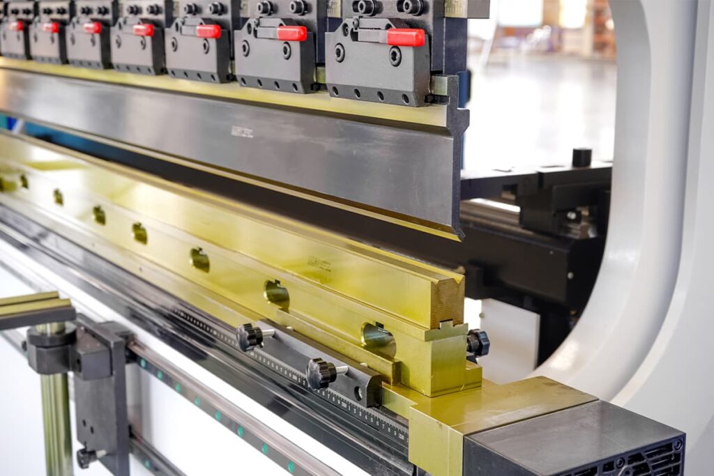
The next step is to set up the machine for calibration. This includes setting the back gauge, bending tool, and clamps.
Back gauge calibration is a process that aligns and checks the accuracy of the back gauge. The back gauge is used to fix the metal sheet in the proper bending position. Please adjust the distance between the back gauge and the bending tool to achieve the required length. And the detailed method is just as follows:
Safety first: before starting, ensure the press brake is closed and the power is switched off. Please obey all the safety programs and wear personal protective equipment.
Check the position of the back gauge: ensure the back gauge is in the fully retracted position and allows for maximum clearance for material loading and tooling installation.
Measure the reference distance: choose the known reference distance on the back gauge, such as a fully retracted position or a specific distance from the center line of the bend. Use calibrated measurement tool (such as a dial gauge or laser measuring device) to check the distance accurately.
Compare the measuring results: compare the measured reference distance to the back gauge display. If there is any difference, please note the difference in calibration adjustments.
Access to calibration parameters: access to calibration mode on the CNC controller of the press brake. This may involve the specific combination key and access to the calibration menu via the control surface.
Adjust the back gauge calibration: use the calibration menu, and input your measured difference in the above step. This action can correct the location of the back gauge and align it with the actual reference distance.
Check the calibration: after the calibration adjustment, use the same measuring tool to measure the reference distance again. The distance measured now should match the back gauge controller display value.
Test the different locations: move the back gauge to each location's inner range, and measure each point. Ensure that the display location matches the measured distance precisely.
Clamp and bending tool
The clamp fixes the metal sheet properly. Ensure the bending tool is at its correct angle to produce the required bending angle.
Check ram parallelism
Ram parallelism refers to the ram parallel to the bending surface (press brake’s bedding or workbench).
Use the parallelism meter to measure and adjust.
Crowning
Crowning refers to the curved line on the bed, compensating for the deflection caused by metal sheet pressure during the bending process. To adjust the crowning, please adjust the bedding oil cylinder until it achieves the required curved line.
Step 7 Operate the Complete Testing Run
Use various thicknesses of materials and bending angles to run the whole testing program on the press brake.
Compare the measuring result with the anticipated results to ensure accuracy and repeatability.
Step 8 Keep Calibration Records
Keep the detailed calibration process records, including any adjustments and realized final settings.
The file is very beneficial for future reference and troubleshooting.
Step 9 Maintenance Regularly
Arranging regular maintenance can keep the press brake at its peak. Regularly checking and calibrating the machine aim to maintain accurate and safe operation.
III. Importance of Press Brake Calibration
The calibration of the press brake is of vital importance because it directly affects the quality of metal bending, accuracy, and safety. And here are the main reasons:
Precision and Consistency
Press brake calibration can ensure the machine can bend the metal sheet at a precise and consistent angle.
Accurate bending can generate even parts. Thus the waste parts and the change in the final product can be decreased.
Quality Insurance
the correct calibration can ensure the final bending workpiece can meet the requirement of specification and quality standards.
This is essential for providing products that meet customer expectations and industry regulations.
Safety Insurance
If the press brake is calibrated well, the risk of accidents and injury can be decreased.
In the measuring process, if the press brake is not calibrated or calibrated inexactly, the tool's unexpected movement may be generated, thus bringing danger to the operator.
Cost Saving
A calibrated press brake can reduce the waste of material owing to the small part of defective components.
Besides, accurate bending can decrease the requirement for rework, thus improving efficiency and saving costs.
Prolong the Lifespan
A calibrated press brake can reduce the wear of critical parts, thus prolonging the machine's lifespan. This help avoids expensive failure and downtime.
Optimize Performance
The calibration can ensure the excellent performance and function of the press brake, which is very important for a mass productivity environment.
Customer Satisfaction
Offering continuous, high-quality, and precise components can satisfy customers and establish customer confidence.
Also, it can improve the company’s reputation and bring repeatable business and recommendations.
Improve Efficiency
The correct calibration can benefit the productivity process, reducing downtime caused by reworking and adjusting, which can improve productivity and efficiency.
IV. FAQs
Why is back gauge calibration important?
The back gauge is an important part of the press brake, and its precision is pivotal to consistent and high-quality results.
If the back gauge has not been calibrated, it will produce errors in the bending process, such as parts that are out of tolerance or angle inconsistency.
These errors may lead to the waste of material, part scrap, and costly rework.
How often should I calibrate the press brake?
The frequency of press brake calibration depends on many factors, such as the using condition of the machine, loading ability, and the manufacturer’s advice.
Generally, calibrate the press brake at least once a year.
Mass productivity may require frequent calibration to keep its accuracy.
What phenomenon indicates that press brakes need to be calibrated?
The phenomenon of press brake needs to be calibrated, including inconsistency of bending angle, different bending lengths, and poor bending quality.
If you find a product exists a difference or doubt the precision problem existence, the checking must be arranged.
Does an uncalibrated press brake cause any safety danger?
An uncalibrated press brake may cause severe safety danger, such as accidental tooling movement, part ejection, or equipment failure. Even the operator may get hurt. The correct calibration can ensure safe operation and decrease workplace danger to the maximum.
How long does it usually take for a press brake to be calibrated?
The time of press brake calibration varies according to the intricacy of the machine and the required calibration degree. Generally, the complete calibration process may require a few hours to a whole day. The specific situation depends on the size and condition of the machine.
Can I prolong the calibration interval by maintaining the press brake basically?
Maintaining regular (such as cleaning, lubrication, and proper tool care) can help prolong the interval of press brake calibration. Obey the manufacturer’s maintenance guidelines can optimize the function and precision of the machine.
V. Conclusion
The press brake calibration is a task that requires professional knowledge and precision.
The paramount thing is to prioritize safety when using an industrial mechanism like a press brake.
If you need more confidence in calibration, it is better to seek help from qualified operators or contact the manufacturer's service department.
ADH is a company that has over 20 years of metal sheet fabrication and boosts press brake, laser cutting machines, and shearing machines.
You can browse our products to choose the suitable machine or consult our sales to learn detailed information.
Act now and change your metal sheet industry!