There are a variety of press brakes, such as manual press brakes, hydraulic press brakes, and CNC press brakes.
Currently, the most popular is CNC press brake, also called an electrical hydraulic servo press brake.
The servo system and linear scale of the electrical hydraulic servo press brake can control the accuracy of the machine during operation.
The CNC control system can set all bending parameters to ensure the accuracy of the bending program.
The main body of the press brake consists of two C-shaped frames on the left and right sides.
The bottom workbench and the top crossbeam are connected to the C-shaped frames.
The plunger section is composed of a crossbeam with an top punch and a workbench with a bottom die. The back gauge aims to provide precise positioning functionality.
The components and operation of the press brake are basically the same, merely differences in driving sources and individual parts.
Next, we will take the CNC press brake as an example and provide a detailed description of its components.
Frame
The main structure that supports the entire machine.
It is usually a high strength fully welded C-shaped structure, and composed of vertical plates on both left and right, bed (workbench) and connecting structures.
The depth of frame is equivalent to throat depth, which offers much bending space.
There are also monitoring tools on the frame, which can detect springback and keep it to a minimum.
Ram
The ram, during the process of opening die (the process of separating the upper and lower dies), is a die component which can slide vertically or form a certain angle responding to the opening die direction.
It drives top punch to do reciprocating linear movement relative to the bottom die to achieve bending sheet metal, thus a specific bending angle or arc will be formed.
The movement of ram contains four parts as following: machine homing, rapid drive, working stroke, and slide return.
It can be divided into top parts and bottom parts. And also it is a driving mechanism component, which can applies pressure to the machine.
Besides, the ram is made of steel plate, and can be connected with oil cylinder through piston rod, driven by synchronized hydraulic cylinders on both sides.
The linear scale on the both sides of ram can provide precise positioning for synchronous movement.
With the help of oil cylinder and mechanical stopper, the ram can avoid crowning.
It works with oil cylinder, mechanical stopper and fine adjustment structure to compose ram parts. Via hydraulic pressure, it drives the piston (rod) to move up and down.
The mechanical stopper is controlled and adjusted by the numerical control system.
Workbench
The workbench is the foundation of the press brake. The tool holder for the bottom dies is installed on the workbench.
Workbench is one of the three components in press brake (left and right oil cylinder, workbench, ram), and made of base and pressure plate.
It is operated by a button box (a device for controlling the operation of press brake), and drives motor to move back and forth along with back gauge.
It is controlled by CNC system to determine the moving distance.
There are two ways of movement: one is the downward movement of the top punch, and the other is the upward movement of the bottom die.
The beam drives the ram to exert a force downward, which is evenly distributed.
The crowning mechanism of the press brake workbench can adjust the force distribution accordingly.
When you select one, it is crucial to consider choosing a relatively shorter size while still satisfying the requirements of the machining tasks.
Back Gauge
The back gauge is a paramount part on the press brake, which is used to control and adjust the position and length of the piecework during the bending process.
It locates on the rear of the press brake, and precisely position the workpiece before bending.
Besides, it is driven by different motors and moves on different axes.
The ball screw and timing belt ensure the synchronous movement of the back gauge.
The back gauge is controlled by the CNC controller and can move on 6 different axes.
The R-axis indicates upward and downward movement. The X-axis represents forward and backward movement. The Z-axis indicates left and right movement.
During bending, the workpiece is placed on the die of the workbench. Push the workpiece to fit with the stop finger. The back gauge has many stop fingers connected with the workpiece.
The main function of the back gauge is to limit the movement of the piecework during bending and to ensure that the piecework is bent in the correct position.
It can be controlled and adjusted by motor, servo motor or cylinder.
The operator can set the position and length of the back gauge through the control system of the press brake to meet the bending requirements of different piecework.
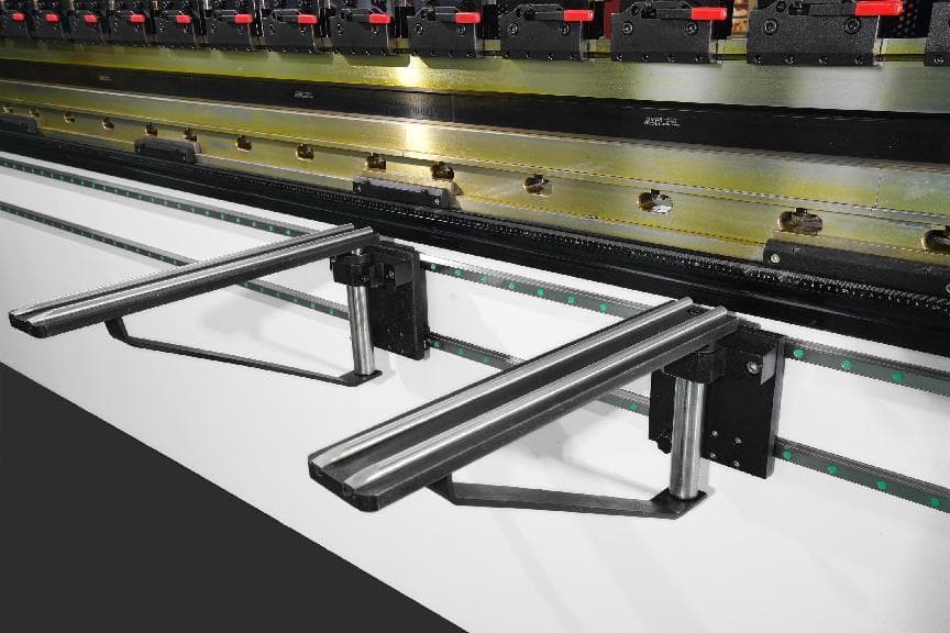
(1) Stop finger
Stop finger is a component that displays the size of the processed piece when the front and back gauge change the displacement.
The stop finger can move smoothly on the linear guide rail, and can also be adjusted up and down, which is convenient, efficient and easy to control.
The press brake generally has multiple stop fingers, according to the actual demand configuration of the number, it is a point contact, and can avoid the problem of insufficient straightness of the plate, realizing the bending of different lengths of sheet metal parts.
(2) Back gauge bar
Back gauge bar is a rod-shaped assembly used with the stop finger to move and adjust the position of the stop finger by electric or hydraulic drive.
The position adjustment of the back gauge bar can be precisely controlled by the control system.
(3) Back gauge sensor
Back gauge sensor is applied to test the position and length of piecework. It can inform the control system position through feedback signal, thus achieving more precise location.
(4) Back gauge controller
Back gauge controller is an electrical device, which used to control back gauge.
It receives the signal from back gauge sensor, and realizes the piecework location adjustment through controlling back gauge bar.
(5) Back gauge guide rails
Back gauge guide rails is a guide rail system installed on the bed, which are used to support and guide the movement of back gauge bar.
And it ensures the bar keeps steady and precise while moving along the bed.
Tool Clamps
Press brake clamps are used to fix the tooling, and are divided into upper clamps and clamps on the workbench.
During the clamping process, the upper clamps can automatically align the center.
Clamps are also divided into ordinary clamps and fast tool clamps.
Fast clamp is a fast clamping and fixing device for top punch on the press brake.
It locates on the ram of press brake and can be used to quick clamping and removal of top punch.
It contains a fixture base and a front pressure plate device, which can adjust the die to ensure even force, prevent ram damage, and ensure the machining accuracy of the workpiece stably.
Punches and Dies
The tooling of the press brake is divided into the punch (top die) and the die.
Punch and die is applied for stamping formation and separation of sheet metal, which makes the piecework into specific shapes and sizes.
The die used for bending depends on bending method, bending angle, raw material, and material thickness.
During bending, the ram drives the top punch to press into the bottom die, which is a bending stroke.
Punches feature right angle dies, acute angle dies, gooseneck dies, etc., and the bottom die has U-shaped dies, V-shaped dies, etc.
Hydraulic System
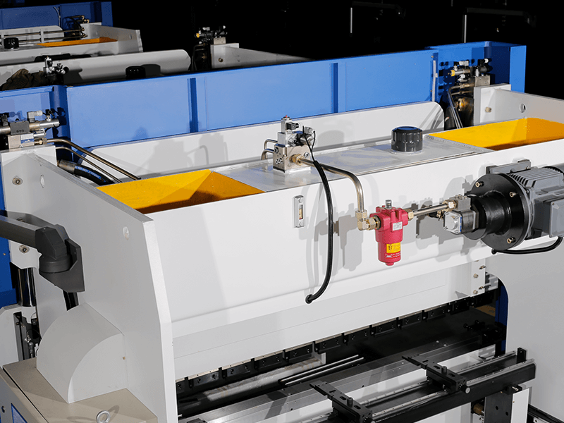
Hydraulic system is used to control the hydraulic cylinder’s pressure and flow rate.
It mainly consists of motor, oil pump, oil filling valve, and oil cylinder, which are mounted on the press brake's frame, and there is an oil cylinder on each of the left and right vertical plates.
The hydraulic pump converts mechanical energy into hydraulic pressure energy to drive the hydraulic system.
The hydraulic cylinder converts the liquid pressure into kinetic energy to drive the ram.
Control System
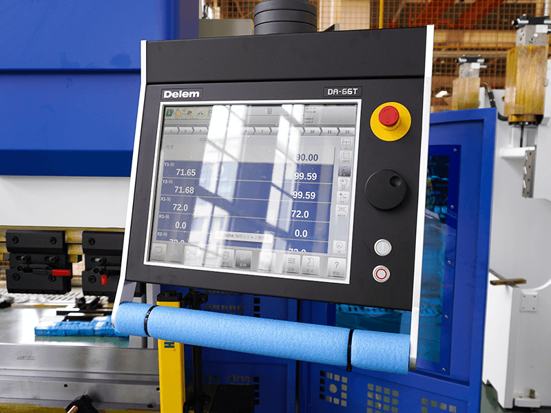
The controller, which serves as the brain of the press brake, receives input commands in the form of text, numbers, symbols, and graphics that make up the machining instructions.
It controls the press brake to execute the machining program. It is able to store diverse programs, and is equipped with interface circuits and servo drive devices.
Controller is applied for setting and controlling the parameters and operations of press brake.
The controller of CNC press brake can control the bending process through programming.
A variety of parameters can be saved in the system. Currently, the most popular controller brands in the market include Delem, ESA, Cyblec, etc.
There are two versions of the controller: button and touch screen. And it provides 2D and 3D graphics programming to simulate the bending process.
Safety Devices
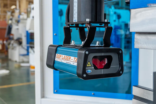
Such as protective covers, emergency stop buttons, etc., which are used to ensure the safety of operators.
And there are safety doors on the both sides of press brake. When the safety doors are closed, the dangerous area on both sides is inaccessible.
When they are opened during operation, all axes will stop moving.
More advanced protection devices include light curtain safety devices and laser protection devices.
Oil Cylinder
Basically, the oil cylinder is composed of cylinder barrel, cylinder head, piston, piston rod, sealing device, cushioning device, and exhaust device. It is fixed on the both sides of press brake, and drives the ram to perform up-and-down reciprocating movement.
Front Support
Front support is used to support metal sheet being bent and can be adjusted up and down.
It is equipped with guide rails and can move automatically. It is more safer and stable compared with manual support, thus achieving better bending results.
Crane Arm
The crane arm is used to hang or support the small control box, which can be turned around in all directions.
It boosts a good load-bearing capacity and a strong and solid structure. It is mostly made of high-quality aluminum alloy with open molding.
Electrical Cabinet
The electrical cabinet is a small low voltage power distribution box, used to enclose electrical wires, measuring instruments, switches, and related equipment in a metal cabinet.
It is compact, and usually installed on the side of the press brake.
Crowning
To ensure the accuracy of piecework and compensation of deformation of ram, the press brake crowning features numerous functions, such as angle crowning, length crowning, gap error crowning, etc.
And it has two crowning ways: hydraulic crowning and mechanical crowning. Mechanical crowning boosts more compensation points, which can make the bending effect to achieve the expected effect, and is durable and stable during use.
Foot Pedal
The foot pedal is one of the four main components (operator, equipment, system, foot pedal) in the operation of the press brake. It integrates emergency stop, cycle, and single-step remote control functions.
The foot pedal allows for the free control of the back gauge left and right movement, as well as the machine's start and stop functions, and integrates control of the machine tool.
What’s more, it can be added with a WIFI module for networking, enabling seamless monitoring and management across the entire area, and offering simplified management capabilities.
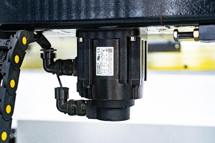
Main Motor
The motor is located next to the filter element and is usually used to provide the driving force and power transmission, such as driving a hydraulic pump or actuator.
Servo Motor
The servo motor applies for the control system of press brake and aims to achieve precise position, speed and torque control.
It is usually connected to the transmission mechanism of the top punch or bottom die for precise bending operation.
Filter Element
The filter element is usually used to filter the liquid in the hydraulic system to keep the hydraulic system working properly.
Linear Scale
Linear scale serves for measuring and controlling the location and angle during bending process. It can be installed on the top punch or bottom die of the press brake.
It is used to measure the location of top punch or bottom die accurately, and control the motion of press brake timely.
Linear scale boosts for its high precision and high definition, which can meet your expected requirements, improving the precision and stability in bending process.
Conclusion
If you are new to press brakes, you can read this article to understand the basic knowledge of press brakes.
ADH's press brakes include CNC press brake, NC press brake, large press brake and robot bending cell.
The bending tonnage ranges from 30 tons to 3000 tons. The controller brands include ESTUN, DELEM, CYBELEC and ESA.
You can browse our products to choose the right machine or consult our sales to learn about detailed information.