The CNC press brake is a kind of press brake controlled by a CNC system.
CNC press brake can fold sheet metals into various profiles.
The bending accuracy and quantity are related to the synchronous system, the hydraulic system and the back gauge.
The function of these press brake components is affected by the number of press brake axes.
This article will introduce the function and working principle of the press brake axes.
What Are the Axes on the Press Brake?
The CNC system controls the movement of the press brake axes.
The press brake axes are named based on their position in the space coordinates.
Press brake axis refers to the mechanical elements which control the different parts’ movement of press brake.
These movements may include up and down movement, back and forth movement, left and right movement, even including the fine adjustment of metal sheet’s bending angle.
The precise movement of axis ensures the accurate position and angle of metal in press brake, facilitating the precise bending operation.
The precision required for the workpiece determines the number of axes needed by the press brake.
Typically, a CNC press brake has at least three groups of control axes: Y1/Y2, X, and R axes.
These are used to control the movement of the back gauge, ram, and other parts.
A torsion shaft press brake can be used to bend simple workpieces with at least two axes, which are used to control the Y-axis of the ram and the X-axis of the back gauge.
The simplest press brake only needs a Y-axis to control the up-and-down movement of the ram.
The accuracy and repeatability of the Y-axis motion determine the accuracy of the bending angle.
The control system uses axes to control the movement of different parts, thereby controlling the bending angle and size.
What Is Back Gauge on the Press Brake?
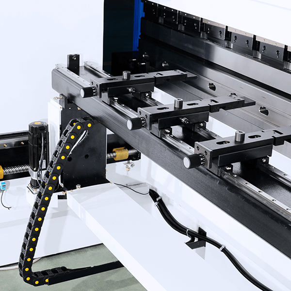
The back gauge of press brake is a component, which helps metal sheet positioning and aligning before its bending. It locates on the rear of bending tool and moves along the X axis.
The back gauge is composed of a series of stop fingers and blocks, which can be adjusted to desired location based on required bending length. These fingers can be operated by manual, electric or CNC system.
Back gauge aims to ensure the metal sheet’s consistence and exact position when bending.
And it realizes the precise bending angle, length and geometric shape via controlling the depth and position between the metal sheet and the bending tool.
It plays a paramount role in improving productivity efficiency, decreasing the equipment setting time and ensuring the repeatability of bending operations.
It eliminates the requirement for manual measuring and suspecting, thus realizing the consistent and efficient bending process.
In modern press brake system, the back gauge can be integrated with the press brake controller to fulfill automatic positioning and controlling. This integration offers seamless cooperation between the back gauge and the press brake axis, facilitating accurate bending operation and precise and repeatable bending.
The back gauge is controlled by the CNC control system to accurately position the sheet metal.
Typically, a back gauge will have at least one axis, and more advanced systems can have up to six axes.
A separate motor drives each axis to slide back and forth in a specific direction.
Ball screw, synchronous belt and axes realize synchronous movement together.
These precise repetitive actions ensure the accuracy of each batch of workpieces.
Optical sensors and CNC programming on the press brake can also be used for positioning.
Relationship Between Back Gauge and Axis
The back gauge of press brake is closely related to the press brake axis, and mutually ensuring the accurate and precise bending operation.
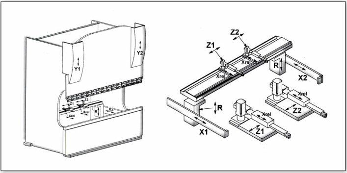
The press brake axis refers to different moving axis inside the press brake, such as X axis, Y axis, Z axis and R axis.
These axes control the positioning of bending tool and movement of metal sheet during bending process.
On the other hand, the position and height of back gauge can be controlled by adjusting the press brake axis.
Trough controlling the position of Y axis and X axis, the back gauge can be aligned with piecework, thus the accuracy and consistence of bending can be ensured.
Nowadays, the back gauge and press brake are usually integrated and controlled by CNC system. This integration allows for automatic positioning and precise controlling between press brake axis and back gauge, achieving an efficient and exact bending process.
Main Groups of Controlled Axis
Y axis
Y axis represents the vertical axis that press brake moves along the depth direction.
The Y axis controls the most important ram part of the press brake.
The ram drives the die to exert pressure on the metal plate through up and down movement.
In air bending, the up and down movement of the top beam becomes stable and uniform driven by Y axis.
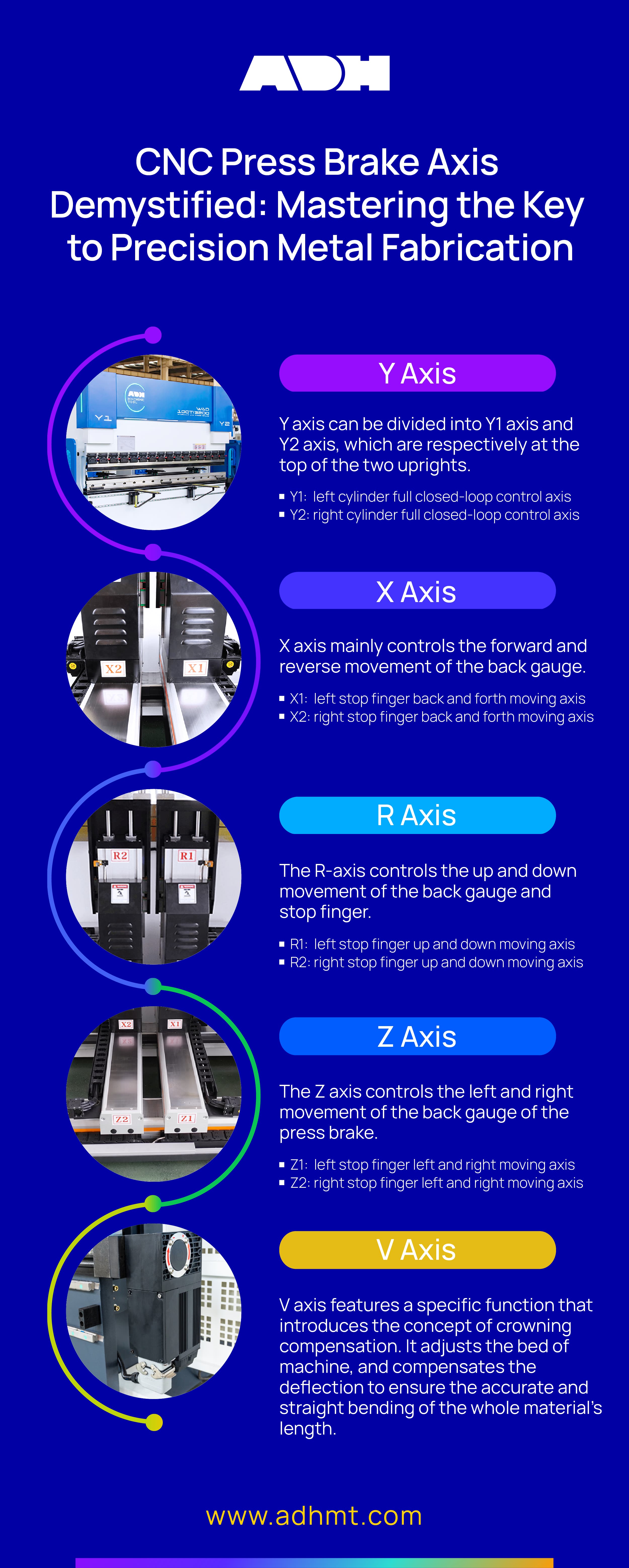
Y axis can be divided into Y1 axis and Y2 axis, which are respectively at the top of the two uprights.
Y1 and Y2 control the up and down movement of cylinders on both sides of the press brake.
The up and down movement of the top beam becomes stable and uniform driven by the Y axis.
Y1 and Y2 are full closed-loop control axes of the left and right cylinders respectively.
Y1 and Y2 can also independently adjust the level of the top beam.
Y1:left cylinder full closed-loop control axis
Y2: right cylinder full closed-loop control axis
Axes on the Back Gauge:
The back gauge determines the bending accuracy of the workpiece.
The more complex the workpiece is, the more axes are required for the back gauge.
There will be at most 6 axes on the back gauge, and these axes will have different variants.
Each axis has a separate drive motor to ensure positioning accuracy.
X axis
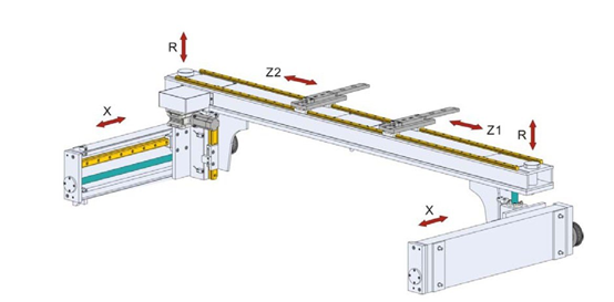
The X axis mainly controls the forward and reverse movement of the back gauge.
X axis is a very important axis in the bending process, which determines the flange length of the workpiece.
When the sheet metal is pushed to the back gauge, the stop finger on the X axis will position the sheet metal.
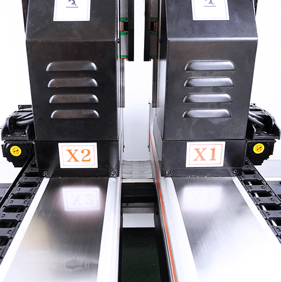
The moving width of axis X on the press brake is fixed, but it can be divided into X1 and X2 axes.
X1 and X2 axes enable the stop fingers of the back gauge to move back and forth independently on the left and right sides.
The X axis controls the forward and backward movement of the back gauge.
As long as the sheet metal enters the back gauge, the stop finger can accurately position the plate.
X1 is the forward and backward moving axis of the left stop finger, and X2 is the forward and backward moving axis of the right stop finger.
The X1 and X2 axes can measure the length of the workpiece flange being formed.
X1: left stop finger back and forth moving axis
X2: right stop finger back and forth moving axis
R axis
The R-axis controls the up and down movement of the back gauge and stop finger.
The height of the R-axis can be automatically adjusted according to the height of the dies. The R axis is divided into R1 and R2.
The two axes can move up and down independently on the left and right sides.
Depending on the complexity of the part, the two axes can be positioned at different distances.
The R-axis can also position the bent flange that moved under the bending plane.
R1: left stop finger up and down moving axis
R2: right stop finger up and down moving axis
Z axis
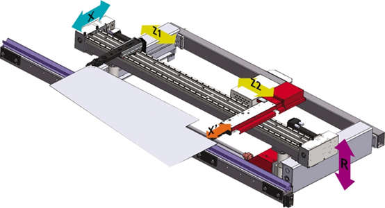
The Z axis controls the left and right movement of the back gauge of the press brake.
The Z-axis is useful when bending a workpiece requires multiple bending steps and cycles.
The Z1 and Z2 axes can be positioned independently through programming.
Positioning with the Z-axis can improve the accuracy and efficiency of bending.
The Z-axis positioning provides uniform support for longer bending sheet metal.
The movement of Z axis determines the horizontal position of back gauge to accommodate the width and horizontal position requirements of different workpieces.
Z1: left stop finger left and right moving axis
Z2: right stop finger left and right moving axis
Other Axes on the Press Brake
In advanced metal fabrication field, press brake plays a pivotal role. Apart from common axes above, there are many additional axes that modern press brakes have equipped to increase controlling and flexibility. Such as V axis, L axis, and Delta X axis.
V axis features a specific function that introduces the concept of crowning compensation.
When bending the long piece of metal, the center usually tends to bow due to the pressure caused by brake, which causes an imperfect bending effect.
In order to eliminate it, V axis adjusts the bed of machine, and compensates the deflection to ensure the accurate and straight bending of the whole material’s length.
L axis controls the horizontal movement of back gauge.
This left and right movement increases the flexibility of handling wider metal sheet or off-center bending.
It adds much flexibility to the press brake operation, especially when dealing with complex accessories and accurate bending operations.
At last, the Delta X axis controls the independent movement of the back gauge fingers, which enables each finger to move independently, and provides tremendous advantages for complex bending operations or asymmetrical parts.
Via adjusting the location of each finger independently, Delta X axis can achieve high precision bending in complex and custom fabrication tasks.
Above all, these axes offer higher precision and accuracy in press brake operation.
Understanding their functions and how to optimize their uses can greatly improve the efficiency, accuracy and overall performance in metal bending and fabrication.
With the constantly development of technology, many advanced axes and functions will be introduced to push the possibility of metal fabrication field.
How to Choose Multi-Axis Press Brake
The number of axes of the press brake determines the complexity and accuracy of the workpiece.
However, the more axes, the higher the cost of machine procurement.
If there are no complex bending requirements, only a basic 3-axis or 4-axis press brake is required.
If complex and precise workpieces need to be processed, the more the number of axes, the better the bending effect.
Conclusion
The bending accuracy of a press brake is determined by the movement of its axes.
A press brake should have at least one Y-axis to control the up and down movement of the ram.
The Y-axis is the most important axis because it controls the bending angle of the workpiece.
The most common press brake is the 3-axis configuration, which is equipped with Y1/Y2, X, and R axes.
When purchasing a press brake, it's important to select the appropriate number of axes based on the complexity of the workpiece.
ADH is a professional press brake manufacturer. Our product experts can help you select the most suitable press brake for your budget.